Facebook
 Google
 GitHub
 Linkedin
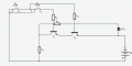
I was trying to build a NAND gate out of transistors but every time I plug in the battery in and press the push buttons the LED still stays on. No matter what I do the LED stays on. Even when i push both buttons the LED still stays on. I've tried different ways to build it but it always ends up where the LED stays on. Can someone explain how to fix this problem and make a NAND gate out of transistors?

Attachments
-
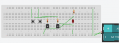 59.2 KB Views: 15
 -
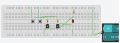 67.1 KB Views: 13


") You have a pretty good eye seeing that spacing difference. My board appears to be larger than the one posted and my rails are connected all the way through,
You have a pretty good eye seeing that spacing difference. My board appears to be larger than the one posted and my rails are connected all the way through,