Facebook
 Google
 GitHub
 Linkedin
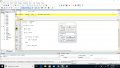
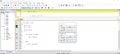
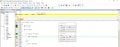
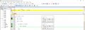
external interrupt : Toggle LED at each press of push buttonProView 32 - an early version of Kiel uVision. The simulator is called ’Debug’. That’s the next thing to learn.
I wrote program to toggle LED at each press of push button but It's not working as it suppose to do. When I press push button LED doesn't toggle
C:
#include<reg51.h>

sbit Switch = P3^7;     //Switch connected to Port P3.7
sbit LED   = P2^0;    //LED connected at output Pin P2.0 */

void main ()
{
     P0 = 0x00;
     P1 = 0x00;
     P3 = 0x80;
    P0 = 0x00;

     EA = 1; // Enable global interrupt */
     EX0 = 1; // External interrupt enable bit //
     IT0 = 1; //Edge triggred mode //
}

void ISR() interrupt 0
{
    LED =~ LED;
}