Why is a bridge rectifier used in a 24V DC input circuit?

Thread Starter

akash.kumar123

Joined Jul 20, 2026
4
Question:

I'm reviewing a 24V DC input protection circuit and I'm trying to understand the design choice of using a bridge rectifier (DB207).


The 24V DC input comes directly from an SMPS, so the input polarity is already fixed and regulated.


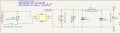
The relevant part of the circuit is shown below.


My understanding of the components is:


  • F1 – Input fuse
  • MOV1 (MOV10D470K) – Surge protection
  • BR1 (DB207) – Full bridge rectifier
  • RV1 (2057-07-BLF) – Surge protection device (not sure if TVS/GDT)
  • D1 (SMBJ36CA) – TVS diode
  • FB1 – Ferrite bead
  • C5, C6, C7 – Input filtering capacitors

My question is:


Since the input is 24V DC coming from an SMPS, the polarity should already be correct. Why is a full bridge rectifier still required?
Wouldn't a reverse-polarity protection MOSFET (or even a single diode) be sufficient if the only concern is accidental reverse wiring?


Is the bridge rectifier being used for one of the following reasons?


  1. To protect against accidental reverse polarity during installation?
  2. To make the board polarity-independent so the input wires can be connected either way?
  3. To make the same PCB compatible with both AC and DC inputs?
  4. Some other industrial design practice that I'm not aware of?

From what I can see, the bridge rectifier ensures the downstream circuitry always sees the correct polarity, but it also introduces a voltage drop of roughly 1.2–1.8V and additional power dissipation. Since the source is already a regulated 24V DC SMPS, I'm curious why the designer chose this approach instead of a lower-loss MOSFET-based reverse polarity protection circuit.


I'd appreciate any insights into the design rationale.
 

Attachments

crutschow

Joined Mar 14, 2008
38,657
Hard to know for sure, but it's likely for one or more of the 1 through 3 reasons you listed.

Certainly if the only thing needing protection is reverse polarity, then a MOSFET circuit would be lower loss.
 

Ian0

Joined Aug 7, 2020
13,211
It’s not so it could take an AC input, otherwise there would be more capacitance.
As it’s a small bridge rectifier, I would assume the current is low enough that the power loss is insignificant. In which case it is for polarity protection, and the bridge was a cheaper choice (or just simpler to understand) than the MOSFET circuit.
 

Parkera

Joined May 3, 2016
128
Most of the components are there to prevent various transients and EMI from getting on the 24V output. RV1 is a 75 volt gas discharge tube. I suppose you could think of that component as akin to a neon lamp. When that fires, its impedance drops to almost nothing, so the transient energy must be absorbed by the total sum of series impedance before the device. That impedance will be the wiring and bridge rectifier. Notice the 100uF capacitor at the output. That is large enough for a low current supply, perhaps 100 mA or less.

Like others have said, "kind of hard to know", but based on the above, my take is that the bridge rectifier is there to make it a universal input: AC, DC+, DC-.
 

MisterBill2

Joined Jan 23, 2018
27,946
My experience has been that it is not possible to mark a connection adequately enough to prevent somebody from connecting the polarity backwards. Thus adding circuitry to allow the correct operation even with the reversal is a good choice. And the first time it prevents damage it becomes a very good choice.
My second thought, 3 days later, is that this input protection scheme is created by AI design software.
 
Last edited:

MisterBill2

Joined Jan 23, 2018
27,946
CERTAINLY "R" makes a serious point!! The circuit shown is OK UNLESS either side of the unseen supply source is "grounded", since the circuit shown has both the NEGATIVE side of the power supply fused AND the negative output of the bridge rectifier tied to the side with what I consider a "ground" symbol attached.
So the circuit as shown is CERTAINLY NOT SAFE from a serious problem!
 

MaxHeadRoom

Joined Jul 18, 2013
30,771
To me, that is a standard Power Common symbol not an Earth Ground.
GND & Earth Ground, Kicad has it right ! :-

1785259131618.png
 
Last edited:

MaxHeadRoom

Joined Jul 18, 2013
30,771
BTW, the sketch appears to be drawn in Kicad, which uses the term GND for thier power common, signal, earth is different.
 
Last edited:

du00000001

Joined Nov 10, 2020
194
In 40+ years I've never seen an MOV and/or GDT in a circuit meant to run from a pre-regulated DC supply - a correctly sized TVS diode is sufficient.
So this circuit might initially have been designed to run from an AC voltage (e.g. 24 V transformer). When regulated DC supplies became cheaper and smaller than transformers, this circuit just survived the transition although it's now somewhat "overspecified".
 

MisterBill2

Joined Jan 23, 2018
27,946
I regard it as totally incorrect to equate "common" with "ground". A circuit's "common" might be intentionally tied to "ground", but in quite a few instances it should not be tied to ground. The reason is that with an intentionally grounded system an unintended "ground" can produce either an incorrect input signal or a system shorted circuit fault or failure.
 

kiroma

Joined Apr 30, 2014
122
When I see circuits that even after several thoughts I can't understand why such design is strange and I know other similar common circuits that does the job, I get more sure that it is poorly designed, be it AI or not.
 

MisterBill2

Joined Jan 23, 2018
27,946
When I see circuits that even after several thoughts I can't understand why such design is strange and I know other similar common circuits that does the job, I get more sure that it is poorly designed, be it AI or not.
I have recently seen that in a thread about a "PEAVEY amplifier problem!!

CERTAINLY there are a few poorly designed circuits that do function correctly, often because others see the flaw and work around it.
 
Last edited:

kiroma

Joined Apr 30, 2014
122
I have recently seen that in a thread about a "PEAVEY amplifier problem!!
Cheap brands, I think, are starting to cut costs putting AI in the place of an engineer, thinking it's going to be awesome. It's recent that people were being laid off because of this kind of situation in other companies, and although I don't have the confirmation for it to be true in hardware design, I can infer that by the situation that's happening. Looks like we'll have to wait some years more to see the products flooding the market with all types of components and topologies misuses.
 

Thread Starter

akash.kumar123

Joined Jul 20, 2026
4
Thank you everyone for the detailed replies and explanations.

I understand from the discussion that the bridge rectifier may be used for reverse-polarity protection, input protection, or possibly to allow the circuit to tolerate either AC or DC input.

For some additional context, this is a 24 V DC input device, and the system is currently working reliably in the field. It has been running continuously for around one year without any fault or failure.

My main question is about the design choice rather than a problem with the existing circuit. If the bridge rectifier was selected mainly because it is a simple and cost-effective solution for reverse-polarity protection, that would also help me understand the design decision.

If cost was an important factor, I would also be interested to know whether there is any significant practical advantage of using the bridge rectifier over a MOSFET-based reverse-polarity protection circuit in a product like this.

Thanks again for all the technical input.
 

Thread Starter

akash.kumar123

Joined Jul 20, 2026
4
I am using a 24 V DC input for my device. Can I continue with the existing input protection design, or should I change it?

Specifically, instead of using the bridge rectifier, can I use a series Schottky diode for reverse-polarity protection while keeping the fuse, TVS diode, ferrite bead, and filter capacitors for surge and EMI/noise protection?

Would this be a suitable and reliable design for a 24 V DC input?
 

kiroma

Joined Apr 30, 2014
122
My main question is about the design choice rather than a problem with the existing circuit. If the bridge rectifier was selected mainly because it is a simple and cost-effective solution for reverse-polarity protection, that would also help me understand the design decision.

If cost was an important factor, I would also be interested to know whether there is any significant practical advantage of using the bridge rectifier over a MOSFET-based reverse-polarity protection circuit in a product like this.
IMO I don't think it has any benefit over MOSFET-based solution. The MOSFET one is actually better, but you have to understand more about the topic. Also, MOSFETs suffer from Vth variation from the process, so in low voltages it might become a problem, you have to select the MOSFET carefully.

I am using a 24 V DC input for my device. Can I continue with the existing input protection design, or should I change it?

Specifically, instead of using the bridge rectifier, can I use a series Schottky diode for reverse-polarity protection while keeping the fuse, TVS diode, ferrite bead, and filter capacitors for surge and EMI/noise protection?

Would this be a suitable and reliable design for a 24 V DC input?
If you change for a Schottky diode, you'll get more efficiency in this stage and overall too.
I don't see any drawbacks to this solution for now.
 
Last edited:
Top