Facebook
 Google
 GitHub
 Linkedin
Question:
I'm reviewing a 24V DC input protection circuit and I'm trying to understand the design choice of using a bridge rectifier (DB207).
The 24V DC input comes directly from an SMPS, so the input polarity is already fixed and regulated.
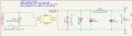
The relevant part of the circuit is shown below.
My understanding of the components is:
My question is:
Is the bridge rectifier being used for one of the following reasons?
From what I can see, the bridge rectifier ensures the downstream circuitry always sees the correct polarity, but it also introduces a voltage drop of roughly 1.2–1.8V and additional power dissipation. Since the source is already a regulated 24V DC SMPS, I'm curious why the designer chose this approach instead of a lower-loss MOSFET-based reverse polarity protection circuit.
I'd appreciate any insights into the design rationale.
I'm reviewing a 24V DC input protection circuit and I'm trying to understand the design choice of using a bridge rectifier (DB207).
The 24V DC input comes directly from an SMPS, so the input polarity is already fixed and regulated.
The relevant part of the circuit is shown below.
My understanding of the components is:
- F1 – Input fuse
- MOV1 (MOV10D470K) – Surge protection
- BR1 (DB207) – Full bridge rectifier
- RV1 (2057-07-BLF) – Surge protection device (not sure if TVS/GDT)
- D1 (SMBJ36CA) – TVS diode
- FB1 – Ferrite bead
- C5, C6, C7 – Input filtering capacitors
My question is:
Wouldn't a reverse-polarity protection MOSFET (or even a single diode) be sufficient if the only concern is accidental reverse wiring?Since the input is 24V DC coming from an SMPS, the polarity should already be correct. Why is a full bridge rectifier still required?
Is the bridge rectifier being used for one of the following reasons?
- To protect against accidental reverse polarity during installation?
- To make the board polarity-independent so the input wires can be connected either way?
- To make the same PCB compatible with both AC and DC inputs?
- Some other industrial design practice that I'm not aware of?
From what I can see, the bridge rectifier ensures the downstream circuitry always sees the correct polarity, but it also introduces a voltage drop of roughly 1.2–1.8V and additional power dissipation. Since the source is already a regulated 24V DC SMPS, I'm curious why the designer chose this approach instead of a lower-loss MOSFET-based reverse polarity protection circuit.
I'd appreciate any insights into the design rationale.
Attachments
-
 173.9 KB Views: 112