Why are my Teensy 4.0 processors dying?

panic mode

Joined Oct 10, 2011
5,057
the 1N5819 diode should go BEFORE the regulator, it does nothing but reduce your Vdd, as placed.
Can you elaborate on this? What would that help with? I guess that would turn it into reverse polarity protection but regulator output would still produce same 5V. Teensy supply can be 3.6-5.5V.

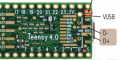
Proposal to add diode there was meant to prevent possible issues that Teensy seem to be affected by when power is applied both by 5V regulator and by USB cable. there is plenty of discussions on this, suggesting alternatives like cutting/soldering pcb jumper on the Teensy, or using switch etc. this way one does not have to modify USB cable or Teensy itself.
1729012230828.png
 

cmartinez

Joined Jan 17, 2007
8,794
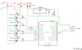
Is this getting closer to a good design? View attachment 333717
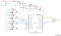
Your circuit should look more like this. Notice the way the input diodes are arranged and the 10uf cap should be placed close to the regulator. The the 5.6V zener at the output should be removed, it's purpose is already been taken care of by the regulator.

1729016883524.png

Word of advice, get rid of R1,R4, R7 and R10, if you're not switching the nFets at high frequencies they serve no real purpose
 

cmartinez

Joined Jan 17, 2007
8,794
Also, I suggest you start learning LTspice for drawing your circuits KiCAD is another option. They're both free and the hell of a lot better than paint for placing parts and editing. Plus you can later learn to simulate your circuits in LTspice
 

Thread Starter

PickyBiker

Joined Aug 18, 2015
144
Also, I suggest you start learning LTspice for drawing your circuits KiCAD is another option. They're both free and the hell of a lot better than paint for placing parts and editing. Plus you can later learn to simulate your circuits in LTspice
Does LTSpice support things like arduino, Teensy?
 

Thread Starter

PickyBiker

Joined Aug 18, 2015
144
Your circuit should look more like this. Notice the way the input diodes are arranged and the 10uf cap should be placed close to the regulator. The the 5.6V zener at the output should be removed, it's purpose is already been taken care of by the regulator.

View attachment 333722

Word of advice, get rid of R1,R4, R7 and R10, if you're not switching the nFets at high frequencies they serve no real purpose
MOSFETs have a gate capacitance that needs to be charged and discharged when switching the MOSFET on and off. When a control signal from the microcontroller (Teensy 4.0 in this case) drives the gate, the resistor limits the amount of current flowing into or out of the gate. This helps avoid excessively high peak currents that could stress the microcontroller's output pins or the MOSFET driver.
 

Thread Starter

PickyBiker

Joined Aug 18, 2015
144
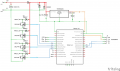
Here is what I hope is the final design. The changes are mostly diodes that were pointing in the wrong direction. (never could keep their directions straight)
1729025268805.png
 

cmartinez

Joined Jan 17, 2007
8,794
Here is what I hope is the final design. The changes are mostly diodes that were pointing in the wrong direction. (never could keep their directions straight)
View attachment 333728
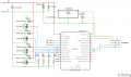
Eliminate the resistor at the top, that's only a hindrance. Also, remove the schottky diode at the right, it really has no use. Also remove R7, R1, R10 and R4. Here's how your circuit should look like

1729026549798.png
 

panic mode

Joined Oct 10, 2011
5,057
voltage regulator keeps on changing:
in post #1 it was 7805
in post #10 it became 7809 (obviously incorrect)
in post #16 it is a TPSM84205EAB (a switching 5V reg.)

also output configuration changed from sourcing to sinking. are you sure this is compatible with your bike? what happens if one tests the bike by simply connecting piece of wire in place of this board? say connecting IDout or RDOut to GND. do lights turn on?

there was mention of 4A current. but this is most likely just steady state, incadescant bulbs have low resistance when cold so current peak can be higher.

what is the wiring method? any chance of things getting shorted or accidentally connected to wrong circuit? maybe some cable pinched...

what exactly is connected to Teensy pins 4/5/6? what voltage level? Is the failre occuring when one of them is triggered? you could measure voltage at those points for both on and off states of each input. this can be done without Teensy connected.
 

Thread Starter

PickyBiker

Joined Aug 18, 2015
144
voltage regulator keeps on changing:
in post #1 it was 7805
in post #10 it became 7809 (obviously incorrect)
in post #16 it is a TPSM84205EAB (a switching 5V reg.)

also output configuration changed from sourcing to sinking. are you sure this is compatible with your bike? what happens if one tests the bike by simply connecting piece of wire in place of this board? say connecting IDout or RDOut to GND. do lights turn on?

there was mention of 4A current. but this is most likely just steady state, incadescant bulbs have low resistance when cold so current peak can be higher.

what is the wiring method? any chance of things getting shorted or accidentally connected to wrong circuit? maybe some cable pinched...

what exactly is connected to Teensy pins 4/5/6? what voltage level? Is the failre occuring when one of them is triggered? you could measure voltage at those points for both on and off states of each input. this can be done without Teensy connected.
The 7809 was a typo. The change from 7805 to TPSM84205EAB was to place a more efficient and cooler power source for the Teensy.

Failures were occurring when the first bulb was activated.

After 4 blown Teensy's, I decided to change the wiring on the bike, so the lights are now lit by pulling the appropriate lead low. This simplifies the turn signal circuit and as you pointed out, it now sinks rather than sources.

Pins 4, 5, and 6 are set as INPUT_PULLUP. They are connected to the bikes directional switch. All 3 of them are 3.3v while inactive and low when active. ssSw is a temporary contact. Whenever the switch is pushed to the left or the right it is low. It is 3.3v again when the switch is released. The other two stay low when the switch is pushed left lsSw, or right rtSw. They are 3.3v again when the switch is pushed in the opposite direction or when the directional switch is pushed in (manual cancel).
Example for left turn:
ssSw =low while the switch is held left and 3.3 when released
lsSw = stays low until the switch is pushed in the opposite direction or the switch is pressed (manual cancel
rtSw 3.3v

The re-wiring of the light system has been tested so that a low on any bulb set causes them to light and the current is about 4.3 amps.

With the latest schematic, I have been receiving advice on what the design should look like and the people on this forum have been very helpful with that.
 
Top