Facebook
 Google
 GitHub
 Linkedin
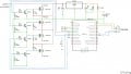
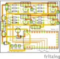
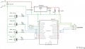
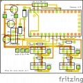
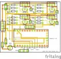
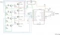
I have a turn signal project that is killing the Teensy 4.0 that it uses. I have gone through 3 of them so far and I just can't see what is causing them to go bad. Here is the schematic and the PCB layout.
Any thoughts on why this is happening would be welcomed.
Any thoughts on why this is happening would be welcomed.
Attachments
-
 267.9 KB Views: 45
 -
 433.9 KB Views: 48