 Facebook
 Google
 GitHub
 Linkedin
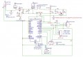
Sincere thanks for reading. I could use a check of my schematic which uses the Teensy 4.0 and the Audio board RevD.
The headers marked U7, U8 are where I'll be connecting a 10k audio volume pot (U7) and a 1/4" audio output jack (U8).
Headers U4 and U5 are for connecting an I2C MPR121 capacitive touch sensor (U4), and an LCD (U5).
Q1 is a p-channel mosfet that is being used for reverse polarity power protection.
Thanks for any input, advice and help.
TonyAm
Attachments
-
 196.4 KB Views: 10


