Whirlpool WEG745H0F gas range repair

Thread Starter

hottubthompson56

Joined Dec 22, 2024
30
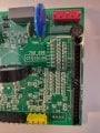
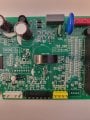
Assuming that the error code is valid, we need to trace the connections around the connector and the cluster of resistors and capacitors. Your photo is not sharp enough.

Visually inspect the pins in the connect

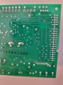
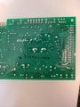
Post new photos of the resistors and capacitors, the full length of the connector, and the reverse side of the board. Make sure that the photos are sharp before posting.

With these, I will be able to give you some test points.
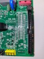
Great. Thanks. I will get back to you all most likely after Christmas
 

MrChips

Joined Oct 2, 2009
34,968
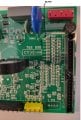
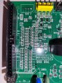
There are two rows of capacitors:

C90
C51
C1
C2
C40
C41
C42
C43

C52
C44
C45
C46
C47
C48
C49

You will need to take voltage measurements while the power is ON. Be careful not to short out anything while making this test. You can leave the touch panel disconnected for this test.

Measure the voltage across each capacitor, with the BLACK lead of the DMM on the left side of the capacitor and the RED lead on the right side of the capacitor. All the capacitors appear to be connected at the left side. (I assume that this is connected to GND.) Hence there is no need to move the BLACK lead. Voltage reading is expected to be between 0 VDC and 5V DC. Get a helper to write down the voltage reading for each measurement.

What is that light brown object between C52 and R112?


Whirlpool inputs.jpg
 

Thread Starter

hottubthompson56

Joined Dec 22, 2024
30
There are two rows of capacitors:

C90
C51
C1
C2
C40
C41
C42
C43

C52
C44
C45
C46
C47
C48
C49

You will need to take voltage measurements while the power is ON. Be careful not to short out anything while making this test. You can leave the touch panel disconnected for this test.

Measure the voltage across each capacitor, with the BLACK lead of the DMM on the left side of the capacitor and the RED lead on the right side of the capacitor. All the capacitors appear to be connected at the left side. (I assume that this is connected to GND.) Hence there is no need to move the BLACK lead. Voltage reading is expected to be between 0 VDC and 5V DC. Get a helper to write down the voltage reading for each measurement.

What is that light brown object between C52 and R112?


View attachment 338877
C90- 5.09 VDC
C51,1,2,40,41,42,43- .729 VDC
C52,44,45,46,47,48,49- 0 VDC

The brown speck must have just been a fleck of something and is gone now.
 

Thread Starter

hottubthompson56

Joined Dec 22, 2024
30
Another clue- when the touchpad was acting up, it was repetitively pressing 'warming zone' which is not a feature of this range. I believe a feature of the electric cook top model. So an unused pin most likely from the outside which would make sense with what portion of the ribbon that was melted to the chassis.
 

MrChips

Joined Oct 2, 2009
34,968
Yes, I am working on the assumption that one of the unused inputs is causing the problem. I am still working on it.

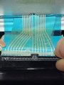
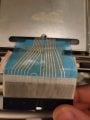
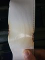
What is showing is a 22-pin ribbon cable going to a 22-pin connector with heat damage on connections 1 and 22. We have to find out what are the functions of these two connections.
 

MrChips

Joined Oct 2, 2009
34,968
With the power off and the appliance unplugged from the wall outlet, measure the resistance across any one of the top resistors, labelled R123, R104 .... R120, R121, R122, R111.

I assume that these are 0Ω resistors but not certain.

There are solder pads for R238 and R244. There is residual solder on those pads which means that the resistors were removed at some point in manufacturing or assembly. Just curious.
 

Thread Starter

hottubthompson56

Joined Dec 22, 2024
30
With the power off and the appliance unplugged from the wall outlet, measure the resistance across any one of the top resistors, labelled R123, R104 .... R120, R121, R122, R111.

I assume that these are 0Ω resistors but not certain.

There are solder pads for R238 and R244. There is residual solder on those pads which means that the resistors were removed at some point in manufacturing or assembly. Just curious.
All those resistors are .511 k ohms.

Pin one seems to run to the larger caps and the tranformed.

Pin 22 runs through R224 and then to pin 18 with a resistance of 13.34 k ohms

Pin 18 goes to R228 and then runs to pin1
 

MrChips

Joined Oct 2, 2009
34,968
The resistors with value code 511 means 510 ohms.
I am asking about the resistors to the right with the dot printed on them.

Can you post a very sharp photo of the lower section above the yellow connector P10 and including ST2?
 

MrChips

Joined Oct 2, 2009
34,968
I will come back to this train of thought in a moment. But first, here is a wild idea.

F2E1 error code is a generic code for a bad switch, even on a microwave oven. Someone fixed error code F2E1 on a microwave oven by replacing a micro-switch.

The only other switch I can find on your gas range is the door switch. Exercise the door and see if it makes a difference.
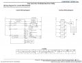
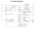
Next, we will try to locate the wiring from the door switch to the control board to see if we can test that it is working properly.

Kenmore gas range.jpg

WEG745H0F.jpg

WEG745H0F Control Wiring Diagram.jpg
 

Attachments

Thread Starter

hottubthompson56

Joined Dec 22, 2024
30
I will come back to this train of thought in a moment. But first, here is a wild idea.

F2E1 error code is a generic code for a bad switch, even on a microwave oven. Someone fixed error code F2E1 on a microwave oven by replacing a micro-switch.

The only other switch I can find on your gas range is the door switch. Exercise the door and see if it makes a difference.
Next, we will try to locate the wiring from the door switch to the control board to see if we can test that it is working properly.

View attachment 338932

View attachment 338934

View attachment 338936
Okay. I will get back to you this evening
 

MrChips

Joined Oct 2, 2009
34,968
Ok, at your convenience.

Disconnect the appliance from the wall outlet.

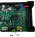
Locate cable going to the black connector P7, to left of the yellow connector.
Measure continuity test at the cable end between pins 4 and pins 5, not at the control board.
Exercise the oven door and ensure that the door switch is functioning correctly.

Door switch connection.jpg
 
Top