WFC Water Fuel Cell by Farlander

Status
Not open for further replies.

Thread Starter

Farlander

Joined Oct 14, 2008
158
Good morning gentlemen and ladies,

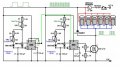
I'm happy to report that over the last couple days I've been able to work rigorously on the WFC. I built the circuit shown under the guidelines of Wook, IBLC and others. I'm waiting on a delivery from jameco for the 10nf caps, 10k pots, and transistors/diodes needed to build a better fet driver.

Question 1, is there any way to get LTSpice (or another prog) to tell you the theoretical frequency of the 555 oscillator?

2- At present, I've used the closest values I had to what was called for. I'm getting good square wave pulse trains although the max frequency and duty cycle are very low, I think because of the newly raised values of R7-R10?

3-The MOSFET gate does not seem to open all the way. When viewed on scope the wave forms are formidably square yet only at max of about 5V. I tried with and w/o D2, no effect. I connected a speaker to the fet drain and negative terminal, and the circuit dies, 0v.

I'm guessing that the source current of pin 3 on the second 555 is not high enough to completely open the gate, and I'll have to wait and build the driver. Any ideas?
 

Attachments

SgtWookie

Joined Jul 17, 2007
22,230
Question 1, is there any way to get LTSpice (or another prog) to tell you the theoretical frequency of the 555 oscillator?
LTSpice should give a reasonable approximation of the frequency.

You can also download 555 Timer Pro and play with it in the freeware mode; it'll work indefinitely that way:
http://www.schematica.com/555_Timer_design/555_Timer_PRO.htm

2- At present, I've used the closest values I had to what was called for. I'm getting good square wave pulse trains although the max frequency and duty cycle are very low, I think because of the newly raised values of R7-R10?
It's because of VR1 thru VR4. They're ridiculously large in comparison to R7-R10.
3-The MOSFET gate does not seem to open all the way. When viewed on scope the wave forms are formidably square yet only at max of about 5V. I tried with and w/o D2, no effect. I connected a speaker to the fet drain and negative terminal, and the circuit dies, 0v.
I'll bet you're using two equal-value resistors for R1 and R2 instead of the values shown. Either that, or you're using a CMOS 555. You could use a CMOS 555 for the 1st timer, but not the 2nd.

As it is, that gate driver circuit won't work very well above around 10kHz. I've already proposed an improved driver circuit - why don't you use it?

Also, as designed, when pin 4 of the 2nd 555 timer is low, pin 7 (discharge) will also be held low. If you have VR3's resistance all the way down, you'll have about 9.3mA current flowing through R9 until pin 4 is again raised (figuring on 14v Vcc/1500 Ohms). This is one of the reasons why I insisted that you raise those values.
 

Thread Starter

Farlander

Joined Oct 14, 2008
158
I think you might be right about CMOS... how do I differentiate? Does CMOS imply 5v?

No the values of R1/R2 are as posted.

I will be building the improved driver circuit once the parts are delivered.


What is the purpose of D2 in the above schematic?
 

SgtWookie

Joined Jul 17, 2007
22,230
I think you might be right about CMOS... how do I differentiate?
The part number.
LM555, NE555, SE555, are BJT.
ICM7555, TLC555, LMC555 are CMOS.
There are LOTS of vendor part numbers for 555 timers. Read the number from the package, then find the datasheet.

Does CMOS imply 5v?
No, but it implies very low source current capability. 10mA is maximum source, 50mA is maximum sink (some are 100mA sink maximum).

No the values of R1/R2 are as posted.
OK, then you must have something else limiting the gate voltage. Try removing any load that you have on the MOSFET's drain, see if it improves. You may just have such a load that when the MOSFET starts to turn on, the power supply gets pulled down to 5v.

What is the purpose of D2 in the above schematic?
D2 is a "flywheel" diode. It provides a current path back through the load for any inductive component discharge when the current path to ground is cut off when the IRF3710 MOSFET is turned off. A 1N4007 diode is really quite undersized, but you shouldn't be getting any current flow anyway, since you're using pure distilled water. If you say there aren't any inductive components, think again - even a straight piece of wire is an inductor.
 

Thread Starter

Farlander

Joined Oct 14, 2008
158
A million thanks as always Sgt. for your knowledgeable and precise reply.
The part number.
LM555, NE555, SE555, are BJT.
ICM7555, TLC555, LMC555 are CMOS.
Oh NOW you tell me! ;) I only seem to have LMC555s, and I just ordered 5 LM555CN.

D2 is a "flywheel" diode. It provides a current path back through the load for any inductive component discharge when the current path to ground is cut off when the IRF3710 MOSFET is turned off. A 1N4007 diode is really quite undersized, but you shouldn't be getting any current flow anyway, since you're using pure distilled water. If you say there aren't any inductive components, think again - even a straight piece of wire is an inductor.
This is very crucial info, thanks. So you're saying that any stored charge in an inductor (or a capacitor??) will discharge back to the positive when the path to ground opens?

Which leads me into the next phase. In actuality, there will be an inductor between the driver and the load, and one between the load and positive. A pair of them, bidirectionally wound on a common ferrite core to be precise. These are the chokes, or "resonant charging chokes" as Meyer described them. But I'm not sure if they are to be wired in parallel or series... the patents show in series:

driver-----coil----- [cathode (WFC) anode]-----coil------- + power

Or parallel
driver------[cathode (WFC) anode]-------- + power
``````| ``````````````````````|
``````| ``````````````````````|
`````Coil ```````````````````Coil

As you can see these diagrams are similar because the coils are not electrically connected, they are coupled by a common core and are weakly connected by the water dielectric insulator.

My theory after recent research suggests that coils in series separate the amp phase from the volt phase by up to 90 degrees. The volts precede and the amps lag. If timed just right, no amps would ever reach the cathode.
This in turn orients the dipolar water molecule, and begins a stretching effect. I just learned this is definitely true when I read an article about how long chains of dipolar molecules can be used in electric coolers. When the chains are electrfied, they orient, causing less entropy which translates to more heat. When the charge is dropped the substance relaxes and begins to cool off. All is needed is a momentary sink to capture the heat.
In our case, the water won't heat up that much because it's not that electrocaloric. Instead, the coils will raise the volts while simultaneously creating a high impredance magnetic field, restricting the flow of amps. The charge will bounce back and forth between the water capacitor and the chokes creating resonant condition, and I am more convinced now a frequency is used to cavitate the water.
The choke coils also cause a type of frequency doubling, when oscillation occurs between the WFC and chokes. A diode on either the positive or negative (or both, the patents conflict) step charges the circuit by blocking the oscillating energy from leaving the system.


Eureka....

Just so you know, I'm not giving up on this until I have exhausted all possibilities or proved it works. I won't forget who helped me out even if it pans out to be false. I'm already farther along than expected because of enviable advisors.

Read more >> Options >>


Last edited:

Thread Starter

Farlander

Joined Oct 14, 2008
158
Good evening
UPDATE:
I built the upgraded 555 driver circuit V3 shown here
http://forum.allaboutcircuits.com/attachment.php?attachmentid=6226&d=1230747976

Still, the MOSFET only outputs 5V (input 12V). I switched fets, no difference. The pulse trains come on at about 5V and gradually decrease to about 4.5V until the next train peaks at 5 again.

Is it possible my new 555s (CHN NE555N) are the low-power CMOS variety?

Could the loading from 1x scope probes cause the drop? I get 12V on the scope when I test the output of the second 555.

It's a very exciting time. I'm getting closer and closer to an experimental prototype each day. Everyone who helps with this will be considered an international superhero and promptly knighted.
 
Last edited:

SgtWookie

Joined Jul 17, 2007
22,230
Good evening
UPDATE:
I built the upgraded 555 driver circuit V3 shown here
http://forum.allaboutcircuits.com/attachment.php?attachmentid=6226&d=1230747976

Still, the MOSFET only outputs 5V (input 12V). I switched fets, no difference. The pulse trains come on at about 5V and gradually decrease to about 4.5V until the next train peaks at 5 again.
Wait - what do you mean, the MOSFET only outputs 5V?
The MOSFET doesn't output anything; it only sinks current.

Is it possible my new 555s (CHN NE555N) are the low-power CMOS variety?
Not with a PN of NE555N.

Could the loading from 1x scope probes cause the drop? I get 12V on the scope when I test the output of the second 555.
Well, that's more or less expected.

It's a very exciting time. I'm getting closer and closer to an experimental prototype each day. Everyone who helps with this will be considered an international superhero and promptly knighted.
Are you royalty? :confused:
 

Thread Starter

Farlander

Joined Oct 14, 2008
158
Not so different right?

Collector = Source --> Ground
Emitter = Drain --> Load
Base = Gate --> Positive voltage input
 

SgtWookie

Joined Jul 17, 2007
22,230
Not so different right?

Collector = Source --> Ground
Emitter = Drain --> Load
Base = Gate --> Positive voltage input
They're different.
MOSFETs are voltage controlled devices. Once the gate is charged or discharged, there is virtually no current required to keep the drain-to-source "connection" open or closed.

Transistors are current controlled devices. For a given current through the base-emitter junction, you get a current through the collector determined by the gain of the transistor.

What does the waveform on the gate of the MOSFET look like, relative to the source?
 

thingmaker3

Joined May 16, 2005
5,083
Lemme make sure I got this wired right -- according to the 2N2907 datasheet, http://www.datasheetcatalog.org/datasheets/50/73874_DS.pdf , pin 3 is the source (to the load), pin 1 is the gate, and pin2 is the drain, (to ground) right?
Second error can be corrected by using the proper datasheet: http://www.datasheetcatalog.org/datasheet/irf/irf1405.pdf A completely different animal, as the Sergent has already explained.

Third error can be corrected by hooking the source to ground and the drain to the load. I suggest you read this: http://www.fairchildsemi.com/an/AN/AN-9010.pdf
 

Thread Starter

Farlander

Joined Oct 14, 2008
158
Buen dia
I got a lot of things figured out today, including that I am still a lot farther from water fuel than I tend to imagine...
The transistor and the MOSFET are both working properly now ( I think). There are problems with the way I orginally wired it, which, may have damaged the MOSFETS in the process. There was a bit of sparking at one point, and excesssive heat build up, to wear it burned my skin to touch the backplate. I'm using twist ties as leads which I'm sure are not recommended.

The circuit performed beautifully during a short test run. Gas output was far higher than expected. Performance was better with the pulsed circuit then power source alone. A ringing could be detected and I could tune the circuit by ear.

Do you have any suggestions for where I might find a small, isolated transformer? Could the transformers in small, common power supplies be isolation? I'm thinking unless I wind one of these myself I'm going to need to harvest one.

A new phenomenon... when I have my oscope negative probe hooked to the fet drain, and I have positive probe to positive, I can see the 60hz AC mains sinewave imposed over my wave... wtf?
 

SgtWookie

Joined Jul 17, 2007
22,230
The transistor and the MOSFET are both working properly now ( I think).
Your O'scope and the datasheets should give you a clear picture of whether or not they are working within specifications.

There are problems with the way I orginally wired it, which, may have damaged the MOSFETS in the process. There was a bit of sparking at one point, and excesssive heat build up, to wear it burned my skin to touch the backplate. I'm using twist ties as leads which I'm sure are not recommended.
Heat and sparks are not good signs.
Twist ties are NOT good electrical conductors. AFAIK, they are made from mild steel, which has roughly 10 times the resistance of an equivalent sized piece of copper wire. So instead of the heat being wicked away from the transistor and MOSFET, it will be heating up their substrates.

Do you have any suggestions for where I might find a small, isolated transformer? Could the transformers in small, common power supplies be isolation? I'm thinking unless I wind one of these myself I'm going to need to harvest one.
You will probably have to wind your own using ferrite toroids.
Stamped-steel E-frame transformers will perform very poorly above a few hundred Hz.

A new phenomenon... when I have my oscope negative probe hooked to the fet drain, and I have positive probe to positive, I can see the 60hz AC mains sinewave imposed over my wave... wtf?
The MOSFET's drain is connected to one of your SS plates. It's picking up ambient noise.
Connect your Oscope's ground (negative) lead to the MOSFET's source terminal, and the + lead to the MOSFET's gate.
 

Thread Starter

Farlander

Joined Oct 14, 2008
158
The time arrives that a step up coil be built. The coil should be an isolation type transformer (no electrical connection between primary and secondary). Torroid or square core it may not matter. The coil should be able to handle 12V 8A pulsed DC (0-60khz) input. It should output approximately 300V. You guys are the experts on this, can you give any figures such as wire guage, number of turns, core diamteter, and material? Cheaper the better. Thanks
:)
 

SgtWookie

Joined Jul 17, 2007
22,230
You're going to have to decide on a minimum frequency for the transformer.
This will help to determine the minimum inductance of the primary side.
If you attempt to operate the transformer at a lower frequency than the specified minimum, it will enter saturation. This will cause a great deal of heat instead of power transfer to the secondary.

The lower the minimum frequency, the poorer the performance will be at higher frequencies.

It is quite likely that you will wind up going through a number of configurations before you find one that you are moderately happy with.

You cannot use garbage like "twist ties" to wind toroidal transformers. You must use proper magnet wire in the gauge specified, and you will most likely have to order it.

You will also need to order a special type of electrical tape to wrap the toroid before winding turns of wire on it.
You'll also need to use this special tape to insulate the layers of windings from each other.

If you're not going to do this properly, I'm really not willing to waste time on it.
 
Last edited:

Thread Starter

Farlander

Joined Oct 14, 2008
158
Fair enough, I accept your challenge I will do this right, patiently and carefully, as you continue to support me with information. I guess we're pretty well into this together now. Yes ok I sometimes I screw up and get too excited I connect "expletive deleted" and turn it on before I know what I'm doing and ask questions later. We're human.

I've committed over a year's effort and at least $200 into the WFC. I see no point in quitting now. I'm quite prepared for the possibility of re-work.

About transformers... is there something special about an air gap between windings? Why not just use a signle rod core?

Also, what is the significance of using stainless steel wire in a winding or choke coil rather than copper? I have been reading mixed reports saying that stainless wire was used in the secondary and/or in the coke coils.

So far I know the core has to powdered ferrite material, i.e. non-permanently magnetic. (I have 3/8" steel all thread??) As for the minimum frequency, 1khz should satisfy, though I really don't understand the circuit resonance as of yet. Because there are 2 square waves superimposed on each other, I suspect there are 2 resonances occurring, possibly the acoustic ring of the electrodes as well as the oscillating electricity. If the former happens to be true, than it may be true that the acoustic frequency of the plates is down in the 200hz range, or lower.

All this should be considered with the knowledge that eventually a resonant scanning circuit needs to be constructed otherwise there's no point. I had an idea today of using a microphone to record the vibrations made by the cell with tubes inside, and amplifying the real time audio signal to switch the FET.
 
Last edited by a moderator:

SgtWookie

Joined Jul 17, 2007
22,230
About transformers... is there something special about an air gap between windings? Why not just use a single rod core?
Toroidal transformers are remarkably efficient, along with having extremely low RF emissions.

Rod transformers have considerable emissions, which will get you in trouble with the FCC. :eek:

Also, what is the significance of using stainless steel wire in a winding or choke coil rather than copper? I have been reading mixed reports saying that stainless wire was used in the secondary and/or in the coke coils.
You've been reading Stanley Meyer garbage. If you want to beleive that resistivity will help in coil windings, then we can stop right here.

So far I know the core has to powdered ferrite material, i.e. non-permanently magnetic. (I have 3/8" steel all thread??)
3/8" steel all thread is so far from powdered ferrite toroid that I can't begin to explain. OK, well, I can.
3/8" steel all thread is a structural material - it has no electrical rating.

Powdered ferrite material varies enormously in it's ratings.

As for the minimum frequency, 1khz should satisfy, though I really don't understand the circuit resonance as of yet. Because there are 2 square waves superimposed on each other, I suspect there are 2 resonances occurring, possibly the acoustic ring of the electrodes as well as the oscillating electricity. If the former happens to be true, than it may be true that the acoustic frequency of the plates is down in the 200hz range, or lower.

All this should be considered with the knowledge that eventually a resonant scanning circuit needs to be constructed otherwise there's no point. I had an idea today of using a microphone to record the vibrations made by the cell with tubes inside, and amplifying the real time audio signal to switch the FET.
So, you want 1kHz to 2kHz? It's going to require a lot of wire.
 

thingmaker3

Joined May 16, 2005
5,083
Commercially available 3/8" threaded rod can be made from a few different compositions of steel. Said compositions are chosen for strength, formability, and machinability. No telling what the magnetic properties might be, other than "lower permeability than iron" and "worse saturability than ferrite."

Stainless steel also comes in a variety of compositions. The ones chosen for wire are typically "austenitic stainless" and have permeability very near unity.

The websites of the manufacturers of ferrite products typically have good technical resources for folk designing coils and transformers. Check them out!
 

Thread Starter

Farlander

Joined Oct 14, 2008
158
Was hoping we could settle this once and for all... the resonance of a series LCL circuit.

Stan claims that voltage does the work. In his patent 4936961 he states:
"As resonance is achieved in any circuit, the amp flow is minimized and voltage is maximized."

The AAC manual says about series LC circuits:
"Extremely high voltages can be formed across the individual components of series LC circuits at resonance, due to high current flows and substantial individual component impedances."

The AAC manual says about parallel LC "tank" circuits that the impedance at resonance tends towards infinity.

If I understand correctly, impedance is the opposition to the flow of current.

So, would infinite impedance allow high voltage at the cell plates?
If so, would we not need a parallel LC circuit?
 
Last edited:
Status
Not open for further replies.
Top