Relays needed to make my central hearing and hot water "smart"

Thread Starter

elsmandino

Joined Mar 3, 2022
11
Hi there.

I am in the process of using a Shelly 2PM (Gen 4) Relay to make my heating/water system, smart. I am then going to use Home Assistant to control it.

I need two relays for the project:

* A mechanical SPDT NO relay, 230v 10A
* A mechanical SPST relay, 230v 10A

Can anyone offer me any advice on what and where to buy (I am in the UK) as these are trickier to find that I had first thought.

Do I need to buy a separate relays and relay holders or can the wires be connected directly to the relays?
 

B-JoJo-S

Joined Jan 3, 2026
474
What is the control voltage? The relay coil? It looks like you're looking for relays that can switch 230VAC with a relay rated to handle up to 10 amps. Are you looking for an SPST NO or NC relay? The SPDT has both NO & NC.

Do you know you can use two SPDT relays? You'll just have one unused pin.
 

Thread Starter

elsmandino

Joined Mar 3, 2022
11
Thanks for this - oddly, it might actually end up cheaper to use two SPDT relays as they seem to be slightly cheaper.

Just to clarify what I am up to:

I currently have this system in my house:

Y Plan central heating system

I have bought one of these ( Shelly 2PM Gen4 - Shelly Europe ) to replace my current water and heating controller.

The heating side is quite straightforward as all it needs is a SPST connection, so I can wire this directly into one of the channels of the Shelly.

The hot water is slightly more tricky as the wiring requires a SPDT switch. As the Shelly only has a SPST, I need to wire a SPDT relay to the hot water wiring and then in turn connect that relay with the Shelly's other channel.

The reason I need an additional SPST relay?

This Y Plan type of heating has a drawback whereby the actuator gets stuck on when you are using the heating only but then turn the heating off - the actuator is designed for this but I have read that by adding a relay like in the attachment, you can significantly extend the life of the actuator.

Hopefully, if I can find the correct relays, it should be quite a simple rewiring job.
 

Attachments

B-JoJo-S

Joined Jan 3, 2026
474
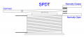
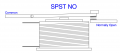
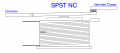
I hate to ask this question - it's not intended to make you feel foolish or uneducated - but do you know the difference between an SPST relay and an SPDT relay? I've prepared some pictures. I think you might be thinking more of a DPDT relay, which I can quickly bang out a picture if needed.
Screenshot 2026-06-03 at 6.41.05 AM.png

Screenshot 2026-06-03 at 6.41.19 AM.png
Screenshot 2026-06-03 at 6.41.53 AM.png
It's important to understand what you need. From your drawing it looks like the control voltage is likely 230VAC. Does your water heater draw 10 amps? (2300W)
 

Thread Starter

elsmandino

Joined Mar 3, 2022
11
Thanks so much for this - please don't worry about making me feel foolish or uneducated (those, who know me, would definitely say I am both ). :)

I am here to absorb all I possibly can and really appreciate the help.

My system is protected by a 3Amp fuse, so I was going with 10A relays to give me a bit of headroom.

Looking at your drawings, I think I definitely need a SPDT for the hot water part of the wiring as it relies on either one or the other part of the circuit being connected at any one time.

With regard to the relay for connecting the hot water to the actuator - I think I need (at a minimum) a SPST NO relay. This should guarantee that when the room thermostat is not calling for heat, the grey wire is not connected and three-port valve returns to its default state (hot water only).

I think the Y-Plan circuitry is very clever but it does give me a bit of headache, each time I look at it.
 

B-JoJo-S

Joined Jan 3, 2026
474
My system is protected by a 3Amp fuse, so I was going with 10A relays to give me a bit of headroom.
Good plan. If anticipating a 3 amp load then the MINIMUM rating for the contacts should be 130% of the load. 150% is better. With some caveat's going with a 10A contact is fine in this case. In some cases you don't want to go overboard. Has an effect on the bottom line AND too large a contact means there's never enough of an arc to clean the contacts. Forget about that - it's just minutia at this point.
I think the Y-Plan circuitry is very clever but it does give me a bit of headache, each time I look at it.
I've never seen this before and it will take me some time to wrap my head around it.

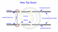
FYI I've banged out an overhead view of a DPDT relay. From the drawing below you can see that in this case there are two contact circuits, each consisting of C, NO & NC (the NO is hidden behind the NC contact, though not exactly labeled). The actuating armature is isolated from the two circuits via an insulator bar. The isolated conductors are flexible braided wire (red) meant to allow the armature free movement. I didn't draw in the spring that holds the armature away from the coil so you have to use a little imagination. The circular parts of the illustration is the coil below the armature.
Screenshot 2026-06-03 at 7.35.34 AM.png
I enjoy drawing mechanical drawings. I've used some differentiating fills to show the difference between conductors that are stationary and those that move.
 

ThePanMan

Joined Mar 13, 2020
950
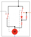
I think they're shown in the motor NOT running position. When power comes on the diode is bypassed. When the motor comes up to speed the centrifugal switches (if that's what they are) switch over and power goes to the motor through two resistors, though I don't know why. At the same time power is routed out to the boiler. I don't even have any idea what the diode does for the circuit. Perhaps at shut-down any BEMF may be stopped by the freewheeling diode. The SPST Mains Relay; What is that doing? Supposed to be doing? If the motor is running then power is passing through two resistors, through the relay and going to the Cylinder Stat (stat port) and to the water heater (HW Off port). It kind of looks like a goldbrick circuit.
 

ThePanMan

Joined Mar 13, 2020
950
Is the motor a Circulating pump? What's the "Call for heat out to pump and boiler" do? OK, it turns the boiler on and turns on a pump. Is this the pump shown in the box?

[edit] If you're in the UK - I didn't know they had a neutral wire on their electrical circuits. UK, as far as I know is a 240VAC service with L1 & L2. No Neutral. In the US the service is split phase 240VAC split to 120 - 0 - 120VAC with L1, N & L2.
 

Thread Starter

elsmandino

Joined Mar 3, 2022
11
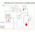
It is really difficult to work out how it all works until you see it in action. The actuator sits on top of a three way valve. The valve's default position sends hot water through my hot tank, the middle position sends water through both my tank and radiators and the third position sends water through my radiators only.

When either is activated, both my boiler and pump are called into action.

I currently have a timer next to the actuator that dictates when hot water and heating run. I want to swap out the timer and put a two channel shelly in its place.

In the Y Plan central heating system wiring diagram, as the Shelly only has a SPST relay built into it, I need a SPDT relay to connect ports 1 and 3 of the "Programmer". The second relay is to fit in as indicated as per my attachment above.
 

MaxHeadRoom

Joined Jul 18, 2013
30,772
[edit] If you're in the UK - I didn't know they had a neutral wire on their electrical circuits. UK, as far as I know is a 240VAC service with L1 & L2.
Domestic supply is fed from one phase of a 3ph transformer, the star point is the grounded neutral.
At least it was when I originally worked and lived there.
 
Last edited:

MisterBill2

Joined Jan 23, 2018
28,042
The drawing of the system is confusing to me, based on how most heatingand cooling systems actually operate. IN the UK you used to have supply companies supporting the various undustrial areas with all of those factories. At least 1n 1985 that was the case. BUT you will need to be able to specify the relay coil voltage, and if it is AC or DC, in addition to the contacts maximum current and voltage ratings.
IN ADDITION, there are a large variety of relays, including quite different reliability levels. AND, there are open-frame relays and enclosed relays. AND, amazingly, there are relay packages intended specifically for heating and cooling applications.
 

MisterBill2

Joined Jan 23, 2018
28,042
And now, visiting this thread again, I am trying to understand what this change does for you as far as improvement or economy. Very fundamentally, there is no way I would want hot water from a heating water loop system to ever mix with water that I might drink or use in food being cooked. Those two schemes have entirely different standards for water purity and cleaness. Those standards are worlds apart.
HAVE YOU EVER seen the water that gets drained out whan a heating radiator gets serviced??

What I am wondering is HOW does the intended change in thesystem arrangement improve either the performance or th efficiency of either the room heating or the water heating. I still get questions about the benefits of changes or the schemes to enhance performance. I have read what was posted and still the benefit mechanism isnot clear to me.
 
Last edited:

B-JoJo-S

Joined Jan 3, 2026
474
In some systems a boiler provides hot water for heating. That same hot water is used to transfer heat to domestic hot water. The two systems share only the heat. Not the same water. I, too, don't understand why he wants to make this change. But my not understanding doesn't mean there's no good reason for it.
 

MisterBill2

Joined Jan 23, 2018
28,042
Back to that question about relays: " Do I need to buy a separate relays and relay holders or can the wires be connected directly to the relays? "
There are more different varieties of relays that there are mixes of dogs. AND more different sizes, as well. I have quite a few of both varieties.
For most heating systems there is a smaller selection, with only a few hundred different styles. For most residential heating and cooling systems, the relays all have 24 volt AC powered coils, and they are the least expensive, usually. Most relays for that sort of system seem to have solder terminals, although quite a few have screw terminal connections.

Now for the really BADNEWS!! neither of the drawings make sense relative to the motor, which the function of that motor is unclear. BUT putting a diode in series with an AC motor does not seem like a good choice.

My guess is that the concept of the plan is to circulate the hot water from the heating system to somehow provide heat to the water in the water heater used for the residential washing use hot water.
A much simpler scheme is to use the returning water from the heating radiators to heat the makup water supply for the washing use hot water.
There is no need to have any electrical control involved if that is the purpose.
 
Last edited:

GetDeviceInfo

Joined Jun 7, 2009
2,284
The 'motor' is a motorized valve with positional output. Quite common . Many different sizes, but small heating systems draw maybe 15 watt.
i can't recommend a source for your relays, but you will likely need a base, which the relays plug into.
 

Ya’akov

Joined Jan 27, 2019
10,278
Welcome to AAC.

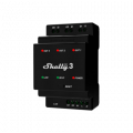
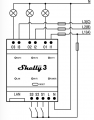
While it will probably cost a bit more, something like the Shelly Pro 3 that provides 3 sets of dry contacts might be a better choice. Dry Contacts means that rather than automatically switching the L input to the outputs, it offers two terminals that are connected when the device is commanded to turn on the output. This will let you accomplish the SPDT function in software. It also has three switch inputs that you could use for whatever you like—they don't have to be related to the switched equipment.

1780996881517.png1780996953667.png
 
Top