Want to make an Electromyography amplifier circuit

Alec_t

Joined Sep 17, 2013
15,132
I'm no expert on EMG, instrumentation amps or filter design, but I would have thought that, at the very least, you would need a deep notch filter to attenuate the local mains frequency drastically. Perhaps a switched-capacitor filter?
It's unfortunate that mains frequency and its low harmonics fall right in the middle of the useful EMG spectrum.
 

Thread Starter

Abhishek Dhiman

Joined Oct 20, 2017
40
I'm no expert on EMG, instrumentation amps or filter design, but I would have thought that, at the very least, you would need a deep notch filter to attenuate the local mains frequency drastically. Perhaps a switched-capacitor filter?
It's unfortunate that mains frequency and its low harmonics fall right in the middle of the useful EMG spectrum.
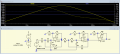
Thank you, sir, for your reply. But can you please check my circuit and tell me whether it is correct or not.
 

Alec_t

Joined Sep 17, 2013
15,132
LTspice. Many members here use it. A free download from Linear Technology.
Yahoo has an LTspice User Group where you can get help and free downloads of model libraries.
 

Alec_t

Joined Sep 17, 2013
15,132
Try it and see: but as I said in post #21, I think you'll need a steep notch filter. Other members may have a better informed view.
 

Thread Starter

Abhishek Dhiman

Joined Oct 20, 2017
40
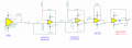
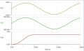
Here is my final amplifier circuit with transient characteristics.
Please check it and suggest me changes.
Will replace INA106 with AD620 in the PCB design.
Final Main circuit precision rectifier.png transient characteristics.png
 

Alec_t

Joined Sep 17, 2013
15,132
Apart from the filter adequacy and output limitation issues already raised, I do wonder if opamp offset errors might be a problem because of the DC coupling between stages.
 

Thread Starter

Abhishek Dhiman

Joined Oct 20, 2017
40
Apart from the filter adequacy and output limitation issues already raised, I do wonder if opamp offset errors might be a problem because of the DC coupling between stages.
How to keep a check on input offset voltage in TL072.
In case of 741 we use a trimpot input voltage compensation but what should I do for Tl072?
 

Alec_t

Joined Sep 17, 2013
15,132
If you use a cap to AC couple to U4's non-inverting input, don't forget to provide a path for the input's bias current, e.g. 100k or so to ground. 1uF should be more than adequate for the cap.
 

Thread Starter

Abhishek Dhiman

Joined Oct 20, 2017
40
If you use a cap to AC couple to U4's non-inverting input, don't forget to provide a path for the input's bias current, e.g. 100k or so to ground. 1uF should be more than adequate for the cap.
Can you please give a circuit diagram that can help me get a better understanding of how to place the ac coupling?
 

AnalogKid

Joined Aug 1, 2013
12,201
I'm no expert on EMG, instrumentation amps or filter design, but I would have thought that, at the very least, you would need a deep notch filter to attenuate the local mains frequency drastically.
Actually, not so much. Besides the amplitude response issues, a notch filter injects lotsa phase distortions for a couple of octaves on each side of the notch. Since the distortions are frequency-dependent, different harmonics of the baseband signal are delayed by different amounts, altering the waveform after the filter compared to before. Proper wire harness design, a well-tuned IA front end, and a linear phase lowpass filter outside the signal bandwidth work well together.

ak
 

AlbertHall

Joined Jun 4, 2014
12,637
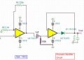
The input to U2 is already AC coupled and as U2 and U3 have DC gains only slightly above unity there should be no problem with the input to U4. However U4 has a DC gain of 100 so its output could have a significant offset which as the circuit stands would be passed on to U5 so I think that it is the input to U5 that needs the AC coupling.
Final Main circuit precision rectifier.jpg
 

Thread Starter

Abhishek Dhiman

Joined Oct 20, 2017
40
The input to U2 is already AC coupled and as U2 and U3 have DC gains only slightly above unity there should be no problem with the input to U4. However U4 has a DC gain of 100 so its output could have a significant offset which as the circuit stands would be passed on to U5 so I think that it is the input to U5 that needs the AC coupling.
View attachment 137982
Thanks a lot sir!
 
Top