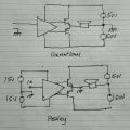
Peavey Bandit 112 amplifier, NFB with two center tapped secondaries.

Thread Starter

Byron Winter

Joined Nov 22, 2024
3
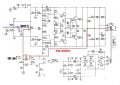
I can't get this amp working. The schematic has 5 different ground symbols, 2 are connected by 47 Ohms. The speaker lies between the two center taps. U4 is driven by the smaller power supply. The signal and its NFB go into U4, (pin 5 and 6) and U4 has no Local NFB. The Peavey Co. doesn't sell a service manual and are otherwise no help. I either get no output from U4 or it slams rail-to-rail. On LTSpice it doesn't work, but that might have something to do with the relationship between the center taps which is undefined. Interesting design, eh ?BanditPwrAmpdetail1.jpg
 

Ian0

Joined Aug 7, 2020
13,203
Floating power supply design. Quite common in power amps of that era as all the small signal stuff can be done with an opamp, instead of high voltage small signal transistors.
If you want to simulate it, give the op-amp ±12v supplies referenced to signal ground.
The output is the centre tap of the transformer. Just model that power supply as a ±50V (or whatever it is, schematic isn’t clear) reference to output, and what would normally be the output (emitters of power transistors) connects to signal ground.

What should happen is when the input signal goes positive, he op-amp output goes negative turning on the PNP transistors, which drags the negative of the ±50V supply towards ground, making the centre tap of the ±50V supply go positive, which delivers a positive voltage to the speaker.

if the output of the op-amp (can’t read its number) deviates from 0V it should turn one set of power transistors on.
 

MisterBill2

Joined Jan 23, 2018
27,888
Certainly that circuit schematic is unconventional, big time!
A bit of a challenge to follow.
My guess is that if that opamp IC is not failed, that there is a problem in the feedback loop, either a leaky capacitor or an open resistor. So checking voltages is in order. AND, any poor connection in the common circuit can cause your observed problem.
ALSO, I suggest checking that large stack of diodes that set the operting bias for all of the following stages.
Consider that many times, when others avoid some design choice, there is a good reason for avoiding it. One diode failing open or short will disrupt the whole circuit. OR even a resistor faling out of tolerance.
 
Last edited:

Thread Starter

Byron Winter

Joined Nov 22, 2024
3
Floating power supply design. Quite common in power amps of that era as all the small signal stuff can be done with an opamp, instead of high voltage small signal transistors.
If you want to simulate it, give the op-amp ±12v supplies referenced to signal ground.
The output is the centre tap of the transformer. Just model that power supply as a ±50V (or whatever it is, schematic isn’t clear) reference to output, and what would normally be the output (emitters of power transistors) connects to signal ground.

What should happen is when the input signal goes positive, he op-amp output goes negative turning on the PNP transistors, which drags the negative of the ±50V supply towards ground, making the centre tap of the ±50V supply go positive, which delivers a positive voltage to the speaker.

if the output of the op-amp (can’t read its number) deviates from 0V it should turn one set of power transistors on.
Thank you. The Op Amp is RC4558D (typical). Supply is +/- 47V. My question remains: Without a Local NFB on the Op Amp, the output would slam rail to rail. Somehow the NFB going into Pin 5 is supposed to prevents this. As the schematic shows, the power amp outputs to the center tap of the 20V secondary and to the speaker negative, while the speaker positive goes to the 35V center tap with part of the voltage going to pin 5. All components between Speaker positive and Pin 5 test good and still I can't get it to work. That leaves only 8 ohms between the two center taps. Maybe my problem with LTSpice is I don't see how to accommodate more than one ground. LTSpice doesn't see the 35V center tap as a ground and my book on LTSpice doesn't cover this. Do you know of any books that I could read? Thanks again.
 

Thread Starter

Byron Winter

Joined Nov 22, 2024
3
Certainly that circuit schematic is unconventional, big time!
A bit of a challenge to follow.
My guess is that if that opamp IC is not failed, that there is a problem in the feedback loop, either a leaky capacitor or an open resistor. So checking voltages is in order. AND, any poor connection in the common circuit can cause your observed problem.
All components check well. I wonder what the range of voltages going to Pin 5 should be. Not to mention the relationship between the two center taps. I know that they can't be connected, but is the 8 ohm speaker enough ? I had to replace the transformer that showed signs of cooking. Thank you.
 
Top