Voltage Divider & Differential Op-Amp

Thread Starter

Tiong

Joined Dec 5, 2019
10
Greetings everyone,

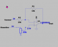
I wanted to build a differential Op-Amp to help eliminate sensor voltage by subtract a preset baseline voltage (supply from voltage divider). After running simulation on LTSpice, it was found out that whenever I connected the voltage divider into the differential Op-Amp circuit, the voltage drop from 2.5V to 2.000006V.

So may I ask everyone here, why is this happening?


Before connecting the voltage divider to the differential circuit:

After.jpeg

After connecting the voltage divider to the differential circuit:

Before.jpeg
 

ericgibbs

Joined Jan 29, 2010
21,390
HT,
On the second circuit, R6 is in parallel with R4 and R3 which are in series.
So R6 equivalent is 6666.6 Ohms.


E
Post your LTSpice asc file.

Mod: Please post Homework questions in the Homework Forum.
 
Last edited:

Thread Starter

Tiong

Joined Dec 5, 2019
10
Greetings ericgibbs,

Ahhhhh now I can see it more clearly. If that the case, in your opinion, what is the best way to inject a baseline voltage without using a voltage divider?

Also sorry that I posted in the wrong forum.
 

ericgibbs

Joined Jan 29, 2010
21,390
Hi T,
As the voltage is an offset correction voltage, what is the purpose of R3?
Also, what is the input impedance on the OPA's non inverting input?

E
 

Ian0

Joined Aug 7, 2020
13,097
What output voltage range do you require?
What input (sensor) voltage range do you wish to map on to the output voltage range?
It might also help to know what the sensor is, because it may have a non-zero output impedance which you have to accommodate.
 

Thread Starter

Tiong

Joined Dec 5, 2019
10
Greetings ericgibbs,

I thought in order for differential Op-Amp to work, we need to set it up as shown below :
1720344968139.png
In my case, my R4 is the picture R2 and my R3 is the picture R4.

And also, may I ask what do you mean by input impedance on the OPA's non inverting input? Sorry I am still quite new in this field.:D
 

Thread Starter

Tiong

Joined Dec 5, 2019
10
Greetings Ions,

My sensors is a TGS2600 gas sensors, which I plan to used to detect gasses. However since I don't know what is the expected output and what is the baseline voltage for it when expose to normal air. Thus, the purpose of making this differential Op-Amp is to:
(i) Use to eliminate the baseline voltage for the TGS2600 gas sensor when expose to clean air.
(ii) Provide amplification so that if the sensor output is too small, I would still be able to amplify it.

I am planning to collect the output to a ESP32/Pi/Arduino (I haven't decided yet). So the operating voltage preferably at 3.3V to 5V> So i guess that voltage range is between 0V to3.3V/5V.


Hope this provide you guys more info. :D
 

Attachments

ericgibbs

Joined Jan 29, 2010
21,390
Hi T,
In post #6 image, what if you connected V2 directly to +5V.?
What would the voltage be on the OPA NI input?
Assume R2 and R4 are 10K
Check the datasheet for the OPA that you are using to determine the input impedance

E
 

Ian0

Joined Aug 7, 2020
13,097
Hi Ian,
It seems that it can be a range determined by.
View attachment 326354View attachment 326355
But when you've got Rs, you need Ro to be able to work out the gas concentrations.
The graphs on the data sheet give the gas concentration related to Rs/Ro.
I presume that one has to run a calibration with clean air at known temperature and humidity to determine it. But wouldn't it be necessary to know the range of Ro in order to design an instrument to use the sensor?
 

ericgibbs

Joined Jan 29, 2010
21,390
Hi,
The d/s suggests that Ro is measured/determined when the sensor is in air.
Then Rload == Ro

Agreed, the project will need to be calibrated before it could be used.

EG57_ 1915.png
 

Thread Starter

Tiong

Joined Dec 5, 2019
10
Greetings ericgibbs,

To reply to post #8, below is the result when supplied 5V and R2 and R4 set as 10k.
1720435541074.png
The input for the Op-Amp is 2.5V. However I wanted the voltage divider as than later I can switch either R5/R6 to a variable resistor so that i can manually adjust the baseline voltage. Do you think I should add a buffer Op-Amp between the voltage divider and the Vbaseline?

Also I just check the datasheet for LM741, the input impedances is around 2M ohm.
 

Attachments

Thread Starter

Tiong

Joined Dec 5, 2019
10
Greetings Ian0,

Yup, what ericgibbs mentioned is correct, that we have to measured it before the experiment can actually start and hence the adjustable baseline voltage (voltage divider) mentioned at post #13. :D
 
Top