Vcc and Gnd connections

Thread Starter

Peter_Runner

Joined Jun 8, 2022
7
Hello everyone,
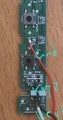
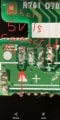
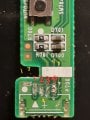
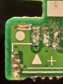
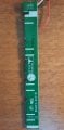
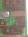
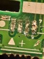
I opened my monitor because there was a problem with setting keys and the menu opened and setting got changed out of my control. I tried to diassemble the key panel to check the keys but this damaged the socket and i need your help to figure out Gnd and Vcc.
I noticed that grnd pin is connected to nowhere in the circuit, is it right or the connection is broken? And last question, how can i test with multimeter if the circuit is damaged or not. Thanks for your help.
 

Attachments

Thread Starter

Peter_Runner

Joined Jun 8, 2022
7
Hi

Here's the pin map (sorry for the awful color)

View attachment 269047
Thanks for your help.
Hi

Here's the pin map (sorry for the awful color)

View attachment 269047
Thanks for your reply. My terminal block broke and damaged the trace pathways so i have to solder the wires directly to the board.
Hi

Here's the pin map (sorry for the awful color)

View attachment 269047

Thanks for your reply. My terminal block broke and damaged the trace pathways so i have to solder the wires directly to the board. I couldnt figure out where 5v input' s trace was connected, it seems nowhere. Can you please help me with this question?
 

Attachments

Ya’akov

Joined Jan 27, 2019
9,069
If the silkscreened marking on the PCB follows convention, and it almost certainly does, then the pin you indicated would be pin 1, and so 5V, based on the white triangular arrow.

As far as testing, test D700 and D701 with the diode test function on your DMM, check each resistor for open or short, or some way off value. Using the continuity function test each switch probing between the arrows on the figure below.

1654760626755.png
 

Ya’akov

Joined Jan 27, 2019
9,069
Many thanks ya'akov, pin number 2 is gnd, and 1 is 5v. Where pin number 1 is connected to? I need to solder a wire. Seems the trace is broken.
To clarify, you are saying that the trace from pin 1 is broken somewhere (failed continuity check) and you need to replace it with a bodge wire?
 

Thread Starter

Peter_Runner

Joined Jun 8, 2022
7
Honestly you are helping a passenger to land an aeroplane !
As it is clear on my photos, the trace from pin 1 which is 5v is broken so i am trying to solder a wire to an element which the pin one has been already connectet to. when i look at it closely, it seems to me that the trace of this pin was not connected to anywhere except itself. Pin number 2 is connected to the thickest trace but what about number 1 ?
 

Attachments

Top