Using a 4N35 Optocoupler - Could use some advice on getting it to work properly

Thread Starter

Mahonroy

Joined Oct 21, 2014
406
Hi guys,
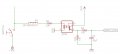
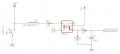
I could use some advice on how to use this 4N35 optocoupler properly. I will describe what I am trying to do, and will attach an image of the circuit.

I have an external switch that is hooked up to +10v dc. My goal is to detect when the switch closes from the +10v line. I am using a parallax propeller micro-controller that has 3.3 volt I/O pins. The threshold for logic 0 or logic 1 is 1.65 volts. I have the input pin tied down to ground via a pull down resistor. When the switch closes, this activates the transistor in the optocoupler allowing the 3.3 volts to flow through; giving me 3.3 volts (about) to the I/O pin, thus giving me a logic 1.

My problem is that when the switch closes, I am only getting about 1.4 volts to the input pin (this then creeps up slowly to about 1.7 volts). So after about 1 second, I get a logic 1, but barely. I was expecting something more closer to 3.3v. Also, when I take a voltage reading at pin 1 of the 4N35 optocoupler, I get about 1 volt there (which I thought was enough volts to activate the transistor inside the 4N35?). I noticed that if I change the resistance of R3 to a lower ohms value, giving me more voltage at pin 1 of the 4N35, that the 10v line starts to get compromised and starts dropping. I was trying to pull as little voltage off the 10v line as possible.

How do you guys think I should handle this? Any help is appreciated, thanks!
 

Attachments

Papabravo

Joined Feb 24, 2006
21,158
Why are you shorting your +10V supply to GND?
When the switch is closed, the LED is dark, and the output transistor is off. The capacitor will discharge slowly to 0.
The RC time constant of the exponential discharge is
Code:
10,100 * 10 e -6 ≈ 101 milliseconds
Describe the behavior you actually want.
 

Bernard

Joined Aug 7, 2008
5,784
Becides the above, what & why is FB? R3 should be around 800 ohms. Why the R-C net?
3.3 V - emitter follower V drop of about .7V = 2.3V.
 

Thread Starter

Mahonroy

Joined Oct 21, 2014
406
Sorry, I made the diagram wrong, I corrected it and re-uploaded it here.

I really just want my micro-controller to know when the 10v is activated on the line from the switch. More specifically, I want the "INPUT_PIN" to read ground when the switch is open, and to read 3.3v when the switch is closed. The resistors and capacitors (R4, R18, and C5) were added as an attempt to try and smooth the signal out slightly (sort of a quick and easy debouncing)
 

Attachments

Papabravo

Joined Feb 24, 2006
21,158
Sorry, I made the diagram wrong, I corrected it and re-uploaded it here.

I really just want my micro-controller to know when the 10v is activated on the line from the switch. More specifically, I want the "INPUT_PIN" to read ground when the switch is open, and to read 3.3v when the switch is closed. The resistors and capacitors (R4, R18, and C5) were added as an attempt to try and smooth the signal out slightly (sort of a quick and easy debouncing)
Then your circuit is all wrong for doing that.
Start with the basics. Don't leave the diode floating, this is bad design. You need a resistor to limit the current in the diode, you cannot connect a diode across a supply this is the road to perdition. Read the datasheet and find the parameter named CTR (Current Transfer Ratio) Use the resistor to set the diode current. Use the switch to ground the Anode of the diode.

Using the value of CTR, multiply the diode current by CTR to figure out how much collector current the transistor will support. Once you get that far we'll talk about the output circuit.
 

Thread Starter

Mahonroy

Joined Oct 21, 2014
406
Then your circuit is all wrong for doing that.
Start with the basics. Don't leave the diode floating, this is bad design. You need a resistor to limit the current in the diode, you cannot connect a diode across a supply this is the road to perdition. Read the datasheet and find the parameter named CTR (Current Transfer Ratio) Use the resistor to set the diode current. Use the switch to ground the Anode of the diode.

Using the value of CTR, multiply the diode current by CTR to figure out how much collector current the transistor will support. Once you get that far we'll talk about the output circuit.
Here is the part for reference:
http://se.mouser.com/ProductDetail/Lite-On/4N35S/?qs=sGAEpiMZZMteimceiIVCBxA0nGdbdemZwNQ//4r1MdE=

So the CTR value is 100%. It says the maximum input diode current is 60mA, so the transistor should support 60mA.
 

Thread Starter

Mahonroy

Joined Oct 21, 2014
406
hi M.
Is that really a 30K from +10V to the opto emitter.?

E

I make that 10V -1.2V = 8.8v/30K approx 0.8mA.!
Yes its a 30k. I found that value just from trial and error (swapping out resistors to see the minimum I could use and still have the opto coupler trigger). Apparently I'm not doing something right though, because this thing in general is not working right haha.
 

Papabravo

Joined Feb 24, 2006
21,158
There is nothing that says you have to use the maximum available current. Let us try for say 15 mA. Oh great your datasheet is in German. I'm guessing the forward voltage drop of the LED is 1.5 Volts. The required resistor is computed as follows.
Code:
((10 Volts) - (1.5 Volts)) / (.015 milliamperes) ≈ 562 Ohms (rounded down to nearest 1% value)
CHECK
8.5 Volts / 562 Ohms = 15.1 milliamps (close enough)
The input side of the opto should be wired according to the following netlist:
+10Votlts - 562 Ohm Resistor(1)
562 Ohm Resistor(2) - 4N35(pin 1) - Switch(pin 3)
4N35(pin 2) - GND
Switch(pin 2) - GND
Notice that the switch is no longer connected directly to the supply. This allows you to short the diode to GND and pulls only 17.8 milliamps through the pullup resistor.
Power dissipation check:
Code:
((17.8 milliamps)^2) * 562 Ohms ≈ 178 milliwatts, Better use a 1/4 resistor, a 1/8th or 1/10th watt resistor won't cut it.
Tell me you understand this much and then we'll move on to the output.
 

Thread Starter

Mahonroy

Joined Oct 21, 2014
406
There is nothing that says you have to use the maximum available current. Let us try for say 15 mA. Oh great your datasheet is in German. I'm guessing the forward voltage drop of the LED is 1.5 Volts. The required resistor is computed as follows.
Code:
((10 Volts) - (1.5 Volts)) / (.015 milliamperes) ≈ 562 Ohms (rounded down to nearest 1% value)
CHECK
8.5 Volts / 562 Ohms = 15.1 milliamps (close enough)
The input side of the opto should be wired according to the following netlist:
+10Votlts - 562 Ohm Resistor(1)
562 Ohm Resistor(2) - 4N35(pin 1) - Switch(pin 3)
4N35(pin 2) - GND
Switch(pin 2) - GND
Notice that the switch is no longer connected directly to the supply. This allows you to short the diode to GND and pulls only 17.8 milliamps through the pullup resistor.
Power dissipation check:
Code:
((17.8 milliamps)^2) * 562 Ohms ≈ 178 milliwatts, Better use a 1/4 resistor, a 1/8th or 1/10th watt resistor won't cut it.
Tell me you understand this much and then we'll move on to the output.
Thanks for the replies so far!

Where are you getting the 1.5 volts from by the way?
I was confused what you meant by "Switch(pin 2) - GND".
So this switch is actually an external device. I'm trying to detect when the switch is pressed on this external device. So I "T"ed off this line and ran it to my device.

Yeah somehow my mouser account got switched to swedish or something. I fixed it, and this should now show the english data sheet:
http://www.mouser.com/ProductDetail/Lite-On/4N35S/?qs=sGAEpiMZZMteimceiIVCBxA0nGdbdemZwNQ//4r1MdE=
 

Papabravo

Joined Feb 24, 2006
21,158
From the Mouser datasheet in German. It is the forward voltage drop of the diode when it is forward biased. Let me see if I can capture the German(Swedish) word.

Maximal framdiodspänning

and the datsheet still isn't in English
 

BigD61

Joined Nov 8, 2014
20
I've worked with 2N217 opcoupler and this would be my approach to sense 10 volt line being active. Since I am not able to upload PDF to this forum, I will attempt a word description. First the LED (diode needs to be forward biased to couple light emissions to the transistor, usually 2 to 5 mA. (.002 to .005 Amps). 8.8V / .004 = 2200 ohms. Connect between the 10V switched line and pin 1. The opcoupler collector pin 5 should tie to the 3.3V supply through a 3300 ohm resistor. This would limit current to .001 amp. The sense line to you micro would junction this point. Opcoupler pins 2 & 4 are tie to ground. Measure voltage at pin 5, if higher than .8 volts re-size diode resistor to value lower. like 2K - 1.8K.
 

Papabravo

Joined Feb 24, 2006
21,158
Thanks Bertus.
Vf for the diode in the 4N35 is 1.2 Volts(typical) and 1.5 Volts(maximum)

From my previous analysis if we use 1.2 Volts as the Vf then the diode current will be
Code:
((10 Volts) - (1.2 Volts))/562 ≈ 15.7 milliamperes
This is till a good place to be for this application.

The schematic symbol for the switch has pins 2 and 3 which are normally open. Pin 3 is connected to the anode of the opto and pin 2 is connected to GND. When the switch is OPEN the pullup resistor allows current to pass through the diode and the LED emits light. When the switch is closed current goes through the resistor and the LED is dark.
 

Thread Starter

Mahonroy

Joined Oct 21, 2014
406
Thanks Bertus.
Vf for the diode in the 4N35 is 1.2 Volts(typical) and 1.5 Volts(maximum)

From my previous analysis if we use 1.2 Volts as the Vf then the diode current will be
Code:
((10 Volts) - (1.2 Volts))/562 ≈ 15.7 milliamperes
This is till a good place to be for this application.

The schematic symbol for the switch has pins 2 and 3 which are normally open. Pin 3 is connected to the anode of the opto and pin 2 is connected to GND. When the switch is OPEN the pullup resistor allows current to pass through the diode and the LED emits light. When the switch is closed current goes through the resistor and the LED is dark.
When the switch is open, current is not flowing from pin 3 of the switch, so the LED should be dark right?
 

Thread Starter

Mahonroy

Joined Oct 21, 2014
406
I've worked with 2N217 opcoupler and this would be my approach to sense 10 volt line being active. Since I am not able to upload PDF to this forum, I will attempt a word description. First the LED (diode needs to be forward biased to couple light emissions to the transistor, usually 2 to 5 mA. (.002 to .005 Amps). 8.8V / .004 = 2200 ohms. Connect between the 10V switched line and pin 1. The opcoupler collector pin 5 should tie to the 3.3V supply through a 3300 ohm resistor. This would limit current to .001 amp. The sense line to you micro would junction this point. Opcoupler pins 2 & 4 are tie to ground. Measure voltage at pin 5, if higher than .8 volts re-size diode resistor to value lower. like 2K - 1.8K.
So you are basically saying that I should swap pin 4 and 5 on the optocoupler.... taking a reading from pin 5 instead of pin 4, and having pin 4 just be ground. Would there be any difference or preferred way between swapping pin 4 and pin 5 around, or is it just personal preference?

Is it necessary to use a capacitor to debounce this signal at all?
 

Papabravo

Joined Feb 24, 2006
21,158
So you are basically saying that I should swap pin 4 and 5 on the optocoupler.... taking a reading from pin 5 instead of pin 4, and having pin 4 just be ground. Would there be any difference or preferred way between swapping pin 4 and pin 5 around, or is it just personal preference?

Is it necessary to use a capacitor to debounce this signal at all?
Will you stop focusing on the output until we get the input squared away?

Follow the netlist I gave you and update the diagram. I don't have Eagle so I can't do it for you. What I want you to do is setup the following situation, you can make changes to your hearts content AFTER you understand what is going on.

1) Connect the power supply through a 562 ohm resistor to the anode of the LED.
2) Connect one terminal of the normally open switch(pin 3) to the anode of the LED.
3) Connect the other terminal of the switch(pin 2) to GND.
4) Pin 1 of the switch is irrelevant, leave it disconnected
5) connect the cathode of the LED to GND.

If you do this, when the switch is open, you will have:
a current of approximately 15 mA flowing through the resistor and the diode to GND. The LED will be emitting light​
When the switch is closed, you will have:
a current of approximately 17.8 milliamps flowing through the resistor to GND. The LED will be dark because no current will flow through it. No current flows through the diode because the voltage at both terminals is the same. Ohms Law -- no voltage drop, no current flow.​
 

BigD61

Joined Nov 8, 2014
20
Regarding using pin 4 or pin 5 as the output. The circuit I offered will give you a clean high/low condition. That is < 1.6 and > 3V Circuit acts like a switch. Taking the voltage off the emitter through a 10K resistor would make the voltage transition very broad, As the current flow through the emitter resistor it makes the emitter become more positive which reverse biases the NPN transistor. Also the 4N35 spec sheet show maximum optical current to be 10 milliamps, so the lowest value resistor value connected between the 10V source and pin 1 is would be 880 ohms. For me that would be 1000 ohms.
 

BigD61

Joined Nov 8, 2014
20
My error, 60 mA is max for the LED, not 10 like I previously stated. A very hi LED current will most likely work with pin 4 as the output.
 
Top