Facebook
 Google
 GitHub
 Linkedin
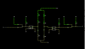
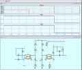
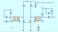
The above circuit I am using for reverse polarity and charger detection circuit for a Battery Management System. Here, I have represented +56V as my charger output. So, I have used two Optocouplers, Left one for reverse polarity detection and right one for charger detection. I have provided two logic output such that the left one should be High when the circuit is detecting reverse polarity connection. The right side logic output is for the charger detection such that if the charger is connected, which I have represented +56V, the logic output is Low and if the charger is not detected Logic is high. Is this circuit correct?


 no charger is connected),