Circuit for Reverse Polarity Detection and Charger Detection using Opto couplers

Thread Starter

Aj01051996

Joined Aug 6, 2026
1
1786074132856.png

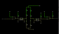
The above circuit I am using for reverse polarity and charger detection circuit for a Battery Management System. Here, I have represented +56V as my charger output. So, I have used two Optocouplers, Left one for reverse polarity detection and right one for charger detection. I have provided two logic output such that the left one should be High when the circuit is detecting reverse polarity connection. The right side logic output is for the charger detection such that if the charger is connected, which I have represented +56V, the logic output is Low and if the charger is not detected Logic is high. Is this circuit correct?
 

AnalogKid

Joined Aug 1, 2013
12,247
Small, low-res image is difficult to read.

Where does the 5 V come from, and does it share a common GND with the 56 V source?

Please add a unique reference designator to each component. without them, the circuit is very difficult to discuss

ak
 

MisterBill2

Joined Jan 23, 2018
28,113
Please avoid showing dotted conductors unless that is used to indicate the active part of some circuit. The difference between circuit and "just lines" is clear to most of us.
Please describe the operation of the circuit as to what happens when:
A:( no charger is connected),
B:(Reveresd polarity is applied),
C:(the charger polarity applied is correct.)
THAT will assure that I understand and can provide a correct evaluation. Presently I do not see how those different conditions will provide signals.
 
Last edited:

ericgibbs

Joined Jan 29, 2010
21,546
hi Aj,
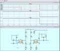
This is what LTSpice simulation shows for your circuit.
Check the layout for accuracy.
E
Edited to show more clearly polarity change.

EG 2173.jpg
 
Last edited:
View attachment 370182

The above circuit I am using for reverse polarity and charger detection circuit for a Battery Management System. Here, I have represented +56V as my charger output. So, I have used two Optocouplers, Left one for reverse polarity detection and right one for charger detection. I have provided two logic output such that the left one should be High when the circuit is detecting reverse polarity connection. The right side logic output is for the charger detection such that if the charger is connected, which I have represented +56V, the logic output is Low and if the charger is not detected Logic is high. Is this circuit correct?
What is the input voltage (Vin) of this circuit?
 
Top