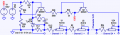
Using a resistor ladder to simulate 16 cells voltage

Thread Starter

kiroviets

Joined May 5, 2026
5
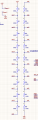
Hello, i'm using a resistor ladder to simulate 16 cells voltage to test adbms1818 chip. Since this testing rig will be running for a few hours i'm worried the resistance will change due to thermal reasons and i can't check if the adc accuracy. Is there a way to stabilize the "cell voltages" so they wouldn't change because of the thermal changes but also would change when i toggle cell discharge (closing a mosfet to discharge the cell through 6 ohm resistor)? Sorry if this is a dumb question with an obvious solve this is my first bigger project.
1782885075815.png
 

Futurist

Joined Apr 8, 2025
882
Hello, i'm using a resistor ladder to simulate 16 cells voltage to test adbms1818 chip. Since this testing rig will be running for a few hours i'm worried the resistance will change due to thermal reasons and i can't check if the adc accuracy. Is there a way to stabilize the "cell voltages" so they wouldn't change because of the thermal changes but also would change when i toggle cell discharge (closing a mosfet to discharge the cell through 6 ohm resistor)? Sorry if this is a dumb question with an obvious solve this is my first bigger project.
View attachment 368916
I wonder if a set of zener diodes might help you achieve a better solution? do any of the loads placed on the various output pins, vary? Also precision foil resistors are very stable, with like +/- 1ppm per deg C
 
Last edited:

dl324

Joined Mar 30, 2015
18,438
Welcome to AAC!
Since this testing rig will be running for a few hours i'm worried the resistance will change due to thermal reasons and i can't check if the adc accuracy.
What is the input impedance of the circuit reading the voltages?

If it's in the megaohm range, you could increase the value of the resistors by an order of magnitude. That would decrease power dissipation, and the associated heating, by an order of magnitude. You'll have to use higher precision resistors (or cherry pick values) for the most accurate results.
 

Thread Starter

kiroviets

Joined May 5, 2026
5
I wonder if a set of zener diodes might help you achieve a better solution? do any of the loads placed on the various output pins, vary? Also precision foil resistors are very stable, with like +/- 1ppm per deg C
No the loads are the same, zener diodes instead of the resistor ladder?


Welcome to AAC!
What is the input impedance of the circuit reading the voltages?

If it's in the megaohm range, you could increase the value of the resistors by an order of magnitude. That would decrease power dissipation, and the associated heating, by an order of magnitude. You'll have to use higher precision resistors (or cherry pick values) for the most accurate results.
Thank you for the warm welcome !
I checked and it's in the megaohm range, but wouldn't using bigger resistors limit me from seeing if the mosfet is working properly by making the voltage drop huge even if the mosfet opens just a little showing me a false positive?
 

Futurist

Joined Apr 8, 2025
882
No the loads are the same, zener diodes instead of the resistor ladder?
You have 50v, and 17 smaller voltage, each a multiple of 50/18 = 2.77v.

(you mentioned 16, but the circuit seems to say otherwise).

Anyway one could string a bunch of Zener diodes of the same voltage, in series, get them all conducting (obviously all reversed biased) with a sufficient supply voltage (with a limiting series resistor) and get a set of 17 voltages, each a multiple of the Zener voltage.

You can buy 2.7v Zener diodes, so one could likely get what you want with a suitable jigged around circuit.

I'm not saying this is a super idea, it just occurred as I was reading your post, precision resistors are probably ideal with hindsight, having just read about temperature stability of Zener's!

Anyway do clarify, are you seeking 16, 17 or 18 different voltages, and what kind of load is each of the voltage pins being subjected to? how did you calculate the 100 ohm value?

Also look at these:

https://www.mouser.com/datasheet/3/40/1/4100R.pdf

The "isolated" variants can easily be wired all in series and because they are all on a tiny chip, they are all likely to always be same temperature
 
Last edited:

panic mode

Joined Oct 10, 2011
5,139
i would just use single LM317 to make constant current source, set it to something like 5mA then add resistors (or trimpots) to dial in specific cell voltages. regardless if using fixed resistors or trimpots, make sure they are not carbon film, use metal film only (thermally stable). or...
use series of 510 Ohm metal film resistors and have single cermet trimpot at LM317 to set current to about 5.29mA (this will produce 2.7V drops across resistors). if your 100 Ohm resistors are metal film type, you can keep them, current will be 27mA. and if your 50V source is not stable, replace top resistor with 27mA current source (LM317 + load resistor about 47 Ohm)
 
Last edited:

Futurist

Joined Apr 8, 2025
882
I must say, prefixing a chip model number with letters ADBMS is weird, searching for this gave all sorts of errors, like insisting I was referring to decibel milliwats. But it is quite an interesting little chip...
 

Thread Starter

kiroviets

Joined May 5, 2026
5
You have 50v, and 17 smaller voltage, each a multiple of 50/18 = 2.77v.

(you mentioned 16, but the circuit seems to say otherwise).

Anyway do clarify, are you seeking 16, 17 or 18 different voltages, and what kind of load is each of the voltage pins being subjected to? how did you calculate the 100 ohm value?
Sorry I didn't notice I took a screenshot of the older scheme. I fixed to 16 resistors and they're at 10k ohm but this value was just a guess. In my mind using a zener diode would get me the needed voltage but when i enable discharge through ADBMS i wouldn't see the voltage drop that tells me that discharging is working, correct me if im wrong.

each pin is connected to a adbms1818 adc and if i read correctly in the datasheet the load is in the MegaOhms
 
Last edited:

dl324

Joined Mar 30, 2015
18,438
I checked and it's in the megaohm range, but wouldn't using bigger resistors limit me from seeing if the mosfet is working properly by making the voltage drop huge even if the mosfet opens just a little showing me a false positive?
Is this really schoolwork?
 

panic mode

Joined Oct 10, 2011
5,139
I fixed to 16 resistors and they're at 10k ohm but this value was just a guess.
do not guess... confirm/measure.


... when i enable discharge through ADBMS i wouldn't see the voltage drop that tells me that discharging is working, correct me if im wrong.
you are not wrong. if only simulating batteries, you need some sort of control. my proposal has that option.

each pin is connected to a adbms1818 adc and if i read correctly in the datasheet the load is in the MegaOhms
i looked it up and this IC has no datasheet. well, there is one on manufacturers website but it is incomplete - just two pages and one of them is blank. it looks like this datasheet was a work in progres for quite some time. if you have something more detailed than the link below, please share it..
https://www.analog.com/media/en/technical-documentation/data-sheets/adbms1816.pdf
 

schmitt trigger

Joined Jul 12, 2010
2,154
Apparently, these chip’s datasheet is following a similar pattern, in which the provided data is deliberately limited. Very sparse.
If one is working with a sufficiently large company, then one should contact the company through an authorized channel, at which point someone will contact you to determine the sales potential and afterwards assign an engineer to implement a turnkey solution for you. Read: not really belonging to you.
This was exactly the business model for a small fabless IC company that I actually interviewed for.
 

Thread Starter

kiroviets

Joined May 5, 2026
5
Is this really schoolwork?
I am a student tasked with this. I can't confirm how this will be used later. It may be used in mass production testing later but that would be my instructor's decision. Is that not allowed to ask in this forum?
 

Thread Starter

kiroviets

Joined May 5, 2026
5
i looked it up and this IC has no datasheet. well, there is one on manufacturers website but it is incomplete - just two pages and one of them is blank. it looks like this datasheet was a work in progres for quite some time. if you have something more detailed than the link below, please share it..
https://www.analog.com/media/en/technical-documentation/data-sheets/adbms1816.pdf
https://www.analog.com/media/en/technical-documentation/data-sheets/adbms1818.pdf do you mean this one?
 

MrAl

Joined Jun 17, 2014
13,745
Hello, i'm using a resistor ladder to simulate 16 cells voltage to test adbms1818 chip. Since this testing rig will be running for a few hours i'm worried the resistance will change due to thermal reasons and i can't check if the adc accuracy. Is there a way to stabilize the "cell voltages" so they wouldn't change because of the thermal changes but also would change when i toggle cell discharge (closing a mosfet to discharge the cell through 6 ohm resistor)? Sorry if this is a dumb question with an obvious solve this is my first bigger project.
View attachment 368916
Hello,

With a series resistor string with the same power in each and every resistor the temperature rise should be able the same, but it is easy to test by swapping resistors and making voltage measurements.
Did you give the power of each resistor? That makes a big difference. If you use 0.125 watt 5 percent resistors at 0.100 watts it would be worse than using 0.25 watt 1 percent resistors at 0.100 watts.
0.25 watt or 0.50 watt would even better.

As to shorting out one 'cell' with a 6 Ohm resistor, that would cause a voltage rise of about 5.5 percent in the unshorted resistors, and if that is too much then you have to use a constant current source, but it should be an accurate, high compliance current source which usually involves at least one op amp. Rather than that however, you may be able to just work the voltage rise into your measurement audits. If you know beforehand the voltage is going to rise by 5.5 percent, then you may be able to work that into the calculations. If it rises by 5.5 percent you know it's working, if it rises by 6 percent or down to 5 percent you might suspect something is not working right. The more accurate number is 5.531 percent and it is a rise once a single resistor is shorted out with a precision 6 Ohm resistor. If the 6 Ohm resistor is not 1 percent also, then measure the value and recalculate the rise in voltage or just get a precision 1 percent resistor or make one using a couple regular value resistors if you can't find a 6 Ohm value.

This assumes that the circuit as is has a 50 volt source that has stable voltage that will not change with a small 6 percent increase in current draw. You could measure that with a decent meter.
 
Top