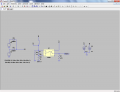
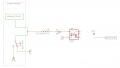
Circuit looks good, but it has reverse logic from desired. When 10V present at pin 1, pin 5 will be low. Sorry my earlier post suggested this configuration.
Circuit looks good, but it has reverse logic from desired. When 10V present at pin 1, pin 5 will be low. Sorry my earlier post suggested this configuration.
To reverse the output polarity, connect the output collector to 3.3V and connect the resistor from the emitter to ground. The signal from the emitter to ground will now be in phase with the input.
Circuit looks good, except I would make the discharge resistor 5.1K . Notice the 1K is loading the 10 volt line. Not sure the circuit need the de-bounce capacitor that large. 1 mfd should do the job.
I think the drop you are seeing is just the way I set up the switch pulses thru the diodes. I real life the switch goes to the 10 volt supply.
Hard to say about the debounce. I think it's about a millisecond.
Will you stop focusing on the output until we get the input squared away?
Follow the netlist I gave you and update the diagram. I don't have Eagle so I can't do it for you. What I want you to do is setup the following situation, you can make changes to your hearts content AFTER you understand what is going on.
1) Connect the power supply through a 562 ohm resistor to the anode of the LED.
2) Connect one terminal of the normally open switch(pin 3) to the anode of the LED.
3) Connect the other terminal of the switch(pin 2) to GND.
4) Pin 1 of the switch is irrelevant, leave it disconnected
5) connect the cathode of the LED to GND.
If you do this, when the switch is open, you will have:
a current of approximately 15 mA flowing through the resistor and the diode to GND. The LED will be emitting light
When the switch is closed, you will have:
a current of approximately 17.8 milliamps flowing through the resistor to GND. The LED will be dark because no current will flow through it. No current flows through the diode because the voltage at both terminals is the same. Ohms Law -- no voltage drop, no current flow.
I updated the diagram, and also changed it slightly to make it more easily understandable of what is going on. I cannot change anything associated with the machine, I can only tap off the wires.
I updated the resistor value, and got rid of the output circuitry. So far, my understanding is that there will be 15 mA going through the opticouplers emitting diode (which can handle a maximum of 60 mA).
My current concern is that this will pull too much current away from the machine. I would like to use the minimum amount of current to activate the optocoupler so I am not obtrusive to the machine.
I think I am reading that the breakdown current is 0.1 mA, is that correct (from the datasheet)? Does this mean that if I want to use the least amount of current as possible, then I can use an 88K resistor?( (10 volts - 1.2 volts)/0.0001 = 88K )
This is why I chose the 30K resistor initially, which is on the previous 2 diagrams. (meaning I am going with a current of 0.293 mA instead of 0.1 mA to be on the safe side)
What I can infer about the unknown circuit is, that it should not contain outputs that will will fight with GND or +10Volts.
On the output side we can do one of two things depending on the sense of the logic.
Assume a resistor R4 of some value we will calculate
Netlist A: Grounded Emitter
+3V3 to R4(pin 1)
R4(pin 2) to 4N35(pin 5)
4N35(pin 6) to GND
When current flows in the LED, and the LED is BRIGHT, the output transistor is ON and current flows from the 3.3V power supply through R4, into the collector, out the emitter to ground. How much current you ask? Depends on R4. There will be some voltage drop across the transistor and we can choose 1.6 milliamps as the collector current.
When no current flows in the LED, and the LED is DARK, the output transistor is OFF. No current flows through the transistor. No current flows through the resitror R4. Quick Ohms Law question: If there is no current flowing through the resistor, what is the VLOTAGE DROP across the resistor? If you answered 0, you are correct. If there is no voltage drop across the resistor then the voltage at the collector of the output transistor must be the supply voltage, namely +3.3 Volts.
Netlist B: Emitter Follower
+3V3 to 4N35(pin 5)
4N35(pin 6) to R4(pin 1)
R4(pin 2) to GND
R4 is still 2.0 K Ohms
Can you work out the fact that in this case the logic is inverted from Netlist A?
What I can infer about the unknown circuit is, that it should not contain outputs that will will fight with GND or +10Volts.
On the output side we can do one of two things depending on the sense of the logic.
Assume a resistor R4 of some value we will calculate
Netlist A: Grounded Emitter
+3V3 to R4(pin 1)
R4(pin 2) to 4N35(pin 5)
4N35(pin 6) to GND
When current flows in the LED, and the LED is BRIGHT, the output transistor is ON and current flows from the 3.3V power supply through R4, into the collector, out the emitter to ground. How much current you ask? Depends on R4. There will be some voltage drop across the transistor and we can choose 1.6 milliamps as the collector current.
When no current flows in the LED, and the LED is DARK, the output transistor is OFF. No current flows through the transistor. No current flows through the resitror R4. Quick Ohms Law question: If there is no current flowing through the resistor, what is the VLOTAGE DROP across the resistor? If you answered 0, you are correct. If there is no voltage drop across the resistor then the voltage at the collector of the output transistor must be the supply voltage, namely +3.3 Volts.
Netlist B: Emitter Follower
+3V3 to 4N35(pin 5)
4N35(pin 6) to R4(pin 1)
R4(pin 2) to GND
R4 is still 2.0 K Ohms
Can you work out the fact that in this case the logic is inverted from Netlist A?
Where did you get the 1.6 mA for the collector current from? And where did you get the 0.1 voltage drop from? I thought the current coming in from the diode side had something to do with the output? (e.g. the CTR value?)
Yes I understand how the Netlist A and Netlist B is basically the same thing.
1.6 milliamperes is one standard TTL load. As such it will drive 1 TTL input, or 4 LSTTL inputs or a whole bunch of CMOS inputs. The Arduino input is a CMOS input and if that is all that is connected to this output then that amount of drive current should be more than sufficient. Now for where CTR comes in. We set the diode current for 15 milliamperes, but whe chose the load resistor in the collector circuit to limit the output current. This means that under all conceivable conditions there will be enough light from the LED to guarantee that the photo transistor is turned on hard. Even if the CTR deteriorates with age there will be sufficient light from the LED to ensure turn on.
0.1 volts is a "typical" Vce voltage drop for an NPN tansistor in the ON condition. You can read the datasheet closely for the actual value, or you can measure it.
Netlist A and Netlist B are not essentially the same circuit. If you line up both circuits you will see that the output of B is the opposite or inverse of A. That is why the circuit is referred to as an emitter follower. The emitter literally follows the input on the base.
A:
Current flows, LED ON, output low (GND)
Current off, LED OFF, output high(+3.3V)
B:
Current flows, LED ON, output high (+3.2V)
Current off, LED OFF, output low (GND)
Now that you understand the basic circuits of optoisolators you can experiment with debouncing and other stuff.
1.6 milliamperes is one standard TTL load. As such it will drive 1 TTL input, or 4 LSTTL inputs or a whole bunch of CMOS inputs. The Arduino input is a CMOS input and if that is all that is connected to this output then that amount of drive current should be more than sufficient. Now for where CTR comes in. We set the diode current for 15 milliamperes, but whe chose the load resistor in the collector circuit to limit the output current. This means that under all conceivable conditions there will be enough light from the LED to guarantee that the photo transistor is turned on hard. Even if the CTR deteriorates with age there will be sufficient light from the LED to ensure turn on.
0.1 volts is a "typical" Vce voltage drop for an NPN tansistor in the ON condition. You can read the datasheet closely for the actual value, or you can measure it.
Netlist A and Netlist B are not essentially the same circuit. If you line up both circuits you will see that the output of B is the opposite or inverse of A. That is why the circuit is referred to as an emitter follower. The emitter literally follows the input on the base.
A:
Current flows, LED ON, output low (GND)
Current off, LED OFF, output high(+3.3V)
B:
Current flows, LED ON, output high (+3.2V)
Current off, LED OFF, output low (GND)
Now that you understand the basic circuits of optoisolators you can experiment with debouncing and other stuff.
Lets say I am doing something similar to Netlist A, but I have the input pin attached to the 3.3 source (after the resistor) instead. Just like in ronv's diagram that he uploaded. What is the proper way to debounce the circuit? (simple debounce with a capacitor)?
The output of the optocoupler is just going to an input pin on a microcontroller (3.3v input). I was not sure if the capacitor should go on the diode side, or on the transistor side.
Change the value of R3 to a standard value 470 ohm resistor.
When the switch closes, the LED will be on.
The transistor is presently configured to be a "follower". The 4N35 output follows the input i.e. "LED on" at the input = "on" (hi) at the output.
Leave the 10K resistor from emitter to ground as shown. Connect the microcontroller to the emitter. (pull the other components; cap and 100 ohm)
Note: When the opto-coupler is "on", the voltage drop across the output transistor can be assumed to be 1.2 volts. So, 3.3 volts minus 1.2 volts = 2.1 volts to the micro.
I see. So you need very little current. So de-bouncing the output would take smaller capacitor.
Do you need the isolation of the opto, or could you just level shift the signal with a little FET?
You need a few ma for the opto because the transfer rato goes down as the diode current goes down.
Which output do you need? The one in phase with the input?
I bread boarded a PS2501 with 470 ohms to 10V source ( 21 milliamps), and with 909 ohm resistor to NPN emitter, voltage measured is 3.1V.
A 909 ohm resistor to the LED will measure 1.6 volts at the same point. Actually .2 volt drop pin 5 to pin 4 means the NPN is near saturation.
I assume you want to isolate the 10 volt source from the micro monitor circuit. The reason for the optic coupler. To achieve lighter loading you would need to add a (PNP) inverting stage to pin 5 of the optic coupler. This would still be > 2 milliamps load to the 10 volt source. I have circuit design to share if someone could teach me how to upload the PDF to this forum. Or you could use 2 discrete transistors with a loading of way less than 1 milliamps to the 10 volt source. Of course circuit has common ground between 10 volt source and Micro monitor.

 Facebook
 Google
 GitHub
 Linkedin

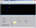 85.4 KB Views: 112