Using 12v brake-light signal as a switch to ground a set of LEDs

Thread Starter

Hellodonk

Joined Nov 2, 2019
6
I just want to start by saying I have some knowledge, being an Industrial designer, but I am by no means an expert.

I have a set of US taillights, that I have successfully converted to UK regulations (yellow indicators) and I am currently working on a dual function tail/brake light feature.

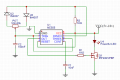
I have built a PWM 555 circuit to lower the brightness of the lights and that works great, however, to get the full 12v to the same lights (to function as brake lights) I am not sure what the best way to go about it is...

In the image attached, the LEDs are hooked up in between the DRL signal and a mosfet. In order to trigger the LEDs full brightness I can ground the negative side of the LEDs, bypassing the mosfet and entire PWM circuit.

But, I would like to use the positive 12v brake light signal already in the car, is there a simple way (another transistor, relay or something similar) to use the 12v signal as a switch to connect the LEDs to ground?

Is there something I'm missing here?
Thanks for any suggestions!
 

Attachments

crutschow

Joined Mar 14, 2008
34,201
Simple.
Just add a diode (1N4148 or similar) between the 12V brake light (anode) and the LED MOSFET gate (cathode).
Thus, when the brake is off, the 555 will control the MOSFET, and when the brake is on, it will override the 555 signal due to the isolation of the 1k resistor, and turn the MOSFET fully on.
 

Thread Starter

Hellodonk

Joined Nov 2, 2019
6
Simple.
Just add a diode (1N4148 or similar) between the 12V brake light (anode) and the LED MOSFET gate (cathode).
Thus, when the brake is off, the 555 will control the MOSFET, and when the brake is on, it will override the 555 signal due to the isolation of the 1k resistor, and turn the MOSFET fully on.

Would that 1N4148 diode be under a lot of current due to the LED draw? Or is that irrelevant?
 

Thread Starter

Hellodonk

Joined Nov 2, 2019
6
No.
It only has to supply about 12mA through the 1k resistor.
The MOSFET gate takes no current.
Okay great, thank you for the help.
Turns out I have a spare diode lying around and have just set it up to test, works great.

However now I have a new problem... This setup allows for dual function lights, but if the DRLs aren't on the brake lights won't do anything. The PWM circuit requires power for the brake lights to work... That's an interesting issue to have!

Sorry I'm just thinking out loud
 

crutschow

Joined Mar 14, 2008
34,201
This setup allows for dual function lights, but if the DRLs aren't on the brake lights won't do anything.
Okay, another couple diodes to the rescue.
Remove the power from the LEDs.
Then add a diode from the DRL power (anode) and a diode from the brake light power (anode) to the anode of the LEDs.
You need larger diodes since they have to carry the LED current.
Do you know how much they take?
 

Thread Starter

Hellodonk

Joined Nov 2, 2019
6
Okay, another couple diodes to the rescue.
Remove the power from the LEDs.
Then add a diode from the DRL power (anode) and a diode from the brake light power (anode) to the anode of the LEDs.
You need larger diodes since they have to carry the LED current.
Do you know how much they take?
So, the brake-light power is going both to the LEDs and the Mosfet from your previous suggestion? While the DRL power is going to the PWM and LEDs?

I'm not 100% sure I follow.

There are 78 12V red LEDs so current should be around 0.45A (I think that's what I measured too)
 

Thread Starter

Hellodonk

Joined Nov 2, 2019
6
Here's a schematic:
Make sense?
View attachment 190478
Okay, so that's what I thought you were saying, glad I'm on the same page.
With the way the lights are wired up (as in the stock taillight wiring that I've been working with), the PWM and DRL are powered by the same input. If that power line runs to both DRL and PWM in the schematic you made, that should work, correct?

Thanks for all the help!
 

crutschow

Joined Mar 14, 2008
34,201
If that power line runs to both DRL and PWM in the schematic you made, that should work, correct?
Yes.
But that does bring up a little problem I didn't catch.
If the DRL is off and the brake is activated, there would be feedback voltage through the PWM resistor to the 555 output which is problematic with the 555 off.
So I added a diode to the signal to prevent that as below:
1572798951854.png
 

Thread Starter

Hellodonk

Joined Nov 2, 2019
6
Yes.
But that does bring up a little problem I didn't catch.
If the DRL is off and the brake is activated, there would be feedback voltage through the PWM resistor to the 555 output which is problematic with the 555 off.
So I added a diode to the signal to prevent that as below:
View attachment 190522
Okay, I have a few questions...

Is that 10k meant to be the 1k from the original schematic? And did you mean to have it grounded?

Am I right in thinking the new diode should be between the 555 output and 1k resistor, or between the resistor and Mosfet base?
 

crutschow

Joined Mar 14, 2008
34,201
Is that 10k meant to be the 1k from the original schematic?
No, it's 10k.
It's to turn the MOSFET off when there's no input, otherwise the gate will float and likely stay on.
Am I right in thinking the new diode should be between the 555 output and 1k resistor, or between the resistor and Mosfet base?
Either would work, but the 1k is not needed.
A MOSFET is not like a BJT.
It has a very high gate input impedance so doesn't need a resistor in series to limit the current.
 

RPLaJeunesse

Joined Jul 29, 2018
252
A word of caution here - don't assume the battery in a car stays near 12V (or more typically 14V while charging). It's not unusual for short term noise on the line to drive it well above "12V", or below ground. (These come from motor inductive kicks, fuses blowing, etc.) A reversed battery - it happens less nowadays - will drive it to -12V or so and sit there until somebody realizes what's wrong. Some tow (service) trucks have used a "double battery jump" to start a car quickly with long jumper cables, so a near steady 24V may happen. If the battery connection opens momentarily while charging the 12V line can go to 45V or more, depending on what clamps it down. There's whole sets of standards for what to expect, I've had to design to these many times so my stuff has survived in heavy-duty police service. Case in point for the above: the gate-source voltage of a FET is typically rated for 20V max, and the circuits proposed above allow that to be exceeded by any noise spike that comes along.
 

crutschow

Joined Mar 14, 2008
34,201
Case in point for the above: the gate-source voltage of a FET is typically rated for 20V max, and the circuits proposed above allow that to be exceeded by any noise spike that comes along.
True, but that's unlikely to happen from the PWM output or during the short time the brake light signal is active.
A 10kΩ gate series resistor with a 12V Zener to ground would protect the gate, if wanted.
 

graybeard

Joined Apr 10, 2012
99
When I design automotive gizmos, I always put a schottky diode in series with the power coming into the gizmo, and right after that, I put an 18V TVS (Transient Voltage Supressor). The diode protects the circuit against reversed polarity and the TVS protects against voltage spikes. The inputs to your gizmo probably should be protected by a TVS as well, depending on the specs of the devices on each input. Alternatively, a series current limiting resistor and two diodes that clamp to each rail could be used for the inputs

One of the nastier situations that can occur is when the alternator is charging the battery and a battery terminal comes loose. All of the current that was going into the battery suddenly needs to find another path to ground, right through your gizmo. That causes a nasty voltage spike that could be hundreds of volts. That is the worst case scenario that I design for.
 
Top