 Facebook
 Google
 GitHub
 Linkedin
Hello,
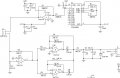
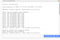
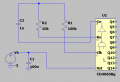
I've been dealing with this circuit for 2 days and I couldn't understand yet. The biggest problem I faced is that I can't simulate this circuit. In general, I use QUCS to simulate circuits but CD4060BM doesn't exist in its library. Therefore, I'm trying EasyEDA but something still goes wrong eventhough I set the circuit correctly. I decided to analyze the circuit part by part. It's not hard to understand the purposes of the OpAmps and the instrumentation amplifier. However, I still can't understand the CD4060BM IC. If I set its connections as in the schematic, errors occured on the inputs 9, 10 and 11. I encounter some problems about the nodes of R1, C4, R5. When I substitute the capacitor C4 with a DC voltage source, no error occurs but can't observe any output both in DC and transient simulation. While using a DC voltage source instead of C4, (-V) is read on 9th input and 0V is read on the inputs 10&11. I can't figure out what's going on. Can you help me understanding this circuit, especially the CD4060BM? I am also open to any suggestions for SPICE softwares.
Thanks, regards...
Attachments
-
 100.7 KB Views: 78
 -
 20.4 KB Views: 67
 -
 37.9 KB Views: 54


")


