Which part do you mean?
If you mean the potentiometer, I explained in the reposted post that in the real circuit, it didn't work that way at all.
If there is another part, please explain
I tested, there was no change
It's interesting, I used two software to simulate the circuits (both Buck and Buck Boost) and tested different values.
But variable resistance does not work in both software
This circuit has a secret
Which part do you mean?
If you mean the potentiometer, I explained in the reposted post that in the real circuit, it didn't work that way at all.
If there is another part, please explain
The variable resistor should have worked, so you probably wired it wrong.
You reconfigured the circuit to a boost topology. The FB network should resolve to 2.5v at the FB pin when the output is at the target voltage. So you need to stop guessing and recalculate the resistance values accordingly.
The problem is when the load is placed on the circuit, in the no load state everything works perfectly
When the load is placed on the circuit, the circuit does not work properly as I explained earlier
The problem is when the load is placed on the circuit, in the no load state everything works perfectly
When the load is placed on the circuit, the circuit does not work properly as I explained earlier
What is the input voltage and What is the target output voltage and current?
What are you using for a load , and what is the load resistance?
Check the Inductor DCR. What shockley diode are you using?
The input voltage has been tested from 18 to 27 volts (15 amps).
The output voltage I need is from 5 to 50 volts.
In buck mode, I don't need more than 15 amps.(Boost 8 amps).
What is "MOSFET protection"?
I have read about it. Is my problem not related to it?
Reverse polarity or overvoltage or...
Please look at the attached pictures
No...I mean DCR (DC resistance). But the inductance would be good to know also.
Any component in series with load has to pass the current delivered to the load.
It may be one of the components is limiting the required current.
No...I mean DCR (DC resistance). But the inductance would be good to know also.
Any component in series with load has to pass the current delivered to the load.
It may be one of the components is limiting the required current.
No...I mean DCR (DC resistance). But the inductance would be good to know also.
Any component in series with load has to pass the current delivered to the load.
It may be one of the components is limiting the required current.
No...I mean DCR (DC resistance). But the inductance would be good to know also.
Any component in series with load has to pass the current delivered to the load.
It may be one of the components is limiting the required current.
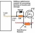
I have a question
According to your formula to calculate the resistance of IC pin 7, at 12V voltage without zener, the resistance should be 460 ohms, but in the schematic it is 4.7 ohms.
Is there another formula for calculating this resistance without a zener?
First, have a look at the clock waveform on pin 4. When you've got that nice and clear on the screen, you know you have the timebase set correctly.
Then have a look at the waveform on pin 6 (the gate drive waveform), which should be a rectangular wave of about 12V amplitude.
If everything looks OK so far, look at the waveform on the MOSFET drain, screenshot it, and post it for us all to discuss (i.e. argue about)
 Facebook
 Google
 GitHub
 Linkedin


![2022-08-16-[09-56-47].jpg](https://forum.allaboutcircuits.com/data/attachments/261/261569-9f52725dde247ea0395ed9c294114738.jpg "2022-08-16-[09-56-47].jpg")
![2022-07-24-[16-21-54].jpg](https://forum.allaboutcircuits.com/data/attachments/261/261570-03248c08d89d0021dfe362f0d750cc7b.jpg "2022-07-24-[16-21-54].jpg")