I believe the circuit should work. It will not like to start a motor. The stall current (startup current) of a motor is much higher than the running current. The supply will current limit and maybe never get a motor started. In current limit mode the MOSFET will run hot.
I believe the circuit should work. It will not like to start a motor. The stall current (startup current) of a motor is much higher than the running current. The supply will current limit and maybe never get a motor started. In current limit mode the MOSFET will run hot.
Hello friends
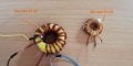
I measured both test cores with LCR meter.
One was 10 and the other 15 microhenries.
I also soldered the circuit on the board to make sure of its connections.
But its output voltage is still correct only on the voltmeter and as soon as a loads is connected to it, the voltage drops below 3 volts.
There is a lamp that loads 12 volts and 20 watts and it is difficult to light up.
There are more than 10 video clips on YouTube that test the same circuit with similar cores, with the loads
The core has 10 or 15 coil turns and the core material is the same that I have used.
Where can the problem come from?
Lamps don't make good test loads, because the inrush current is 10x the running current, and the PSU will have a hard time starting up.
Remind us again what your target output voltage/current was, let's see some waveforms.
Lamps don't make good test loads, because the inrush current is 10x the running current, and the PSU will have a hard time starting up.
Remind us again what your target output voltage/current was, let's see some waveforms.
Yes
The main power supply that is supposed to be connected to this circuit is 27 volts and 15 amps (switching).
I tested the circuit both with this power supply and with 24V 3A and it has the same fault in each.
I need about 50V as a power supply for various tasks (0 to 50V).
In buck mode, I don't need more than 15 amps.
My problem is that this circuit does not work at all.
Except for the voltmeter, it doesn't work with anything I try.
I have been involved in this circuit for a long time, a circuit that works easily with lamps and DC motors in the videos.
So, your input supply is 27V with a maximum output current of 15A?
Don't forget that the peak voltages on the MOSFET and diodes are Vin+Vout in a SEPIC converter.
So, your input supply is 27V with a maximum output current of 15A?
Don't forget that the peak voltages on the MOSFET and diodes are Vin+Vout in a SEPIC converter.
I have used MBR 30100 diode.
Regarding the MOSFET, if you suggest another model, I will try it, of course, I must say about the input voltage, I have tried with any input voltage.
From 10 volts to 27 volts
But I still have the same results
So, your input supply is 27V with a maximum output current of 15A?
Don't forget that the peak voltages on the MOSFET and diodes are Vin+Vout in a SEPIC converter.
The problem is not the coil
I also tried with a coil of 220 μH and the exact same problem still exists
Everything is correct on the voltmeter
But as soon as even a small consumer is connected, the voltage reaches close to zero
The input is 15 amps and the output voltage is zero!!!!!!
I don't know where this amount of voltage and amperage goes
What?
It is very important that the transformer is 1:1.
10:15 is not good.
You need to wind the transformer pulling two wires at the same time. Do not wind two separate windings.
Not like this:
Several times "we" have asked about the phasing on the transformer. Without an oscilloscope it is hard to trouble shoot.
The wire with 12V or 30V on it, and the wire on ground should be on the same end of the transformer.
C8, C9; Under light loads, you can operate without these two caps.
Several times "we" have asked about the phasing on the transformer. Without an oscilloscope it is hard to trouble shoot.
The wire with 12V or 30V on it, and the wire on ground should be on the same end of the transformer.
Yes
I have answered on page 2 of this post with a photo that I am attaching again.
I think the inductors are connected exactly according to your description.
Of course, I have also moved the connections in different ways to be sure and test.
I was able to solve the problem to some extent, of course I think.
I set the resistance of R10 below the value of 0.05.
Now the circuit works, there are only a few problems
For example, we have 6 volts without load, and when the load is connected to it, the voltage first becomes zero and within 2-3 seconds, the voltage reaches about 5.5 volts.
Another problem is that if you remember, I asked about the input of the circuit, how can I give about 30 volts to the input
And the answer was that with an 18V zener and a 680 ohm resistor on pin 7 of the IC, the result can be reached
But now, when the circuit input is more than 18 volts, the MOSFET gets extremely hot
I would be grateful if you could explain to me in a simple way what the permissible voltage between the MOSFET pins should be during use.
I read the MOSFET datasheet and did not understand it
Can you highlight the part of the datasheet that you do not understand? MOSFETs can get hot for a couple of reasons which include but are not limited to:
Inadequate Gate to Source voltage. The gate threshold voltage is the gate to source voltage where the device BEGINS to conduct. In this application you want to turn the gate on very quickly to a voltage that could be much higher than your input voltage. The datasheet should tell what fully on means. It is where rds(on) is a minimum.
SLOW turn on and turn off. During this phase of operation there is Miller effect which arises because of how the MOSFET channel interacts with the node capacitances on the device. Normally you would use a gate driver that can move charge on to and off of the gate just as fast as electronically possible. Any delay in this process because of LONG RC time constants will allow for substantial heating.
There may be other reasons for your problem, but those are two of the big ones. I don't see the schematic in post #54 addressing either of those two concerns.
This shows Vgs(th) to be between 2V and 4V. It also shows rds(on) to be a maximum of 17.5 mΩ with Vgs @ 10V and Id @ 25 Amperes. That is what you should be shooting for.
Another section to look at is the amount of gate charge in Coulombs that you need to put on the gate and take off the gate. Resistors alone will seldom do an adequate job of this.
I leave it to you to figure out how long it takes to charge and discharge the gate to and from 63 Coulombs. If you are not doing it fast enough then you should expect problems.
Nothing wrong with separate windings on the same core for SEPICs and Cuks (but the green core is ferrite, and it won't work without a gap). SEPICs and Cuks don't need coupled inductors to work.
Can you highlight the part of the datasheet that you do not understand? MOSFETs can get hot for a couple of reasons which include but are not limited to:
Inadequate Gate to Source voltage. The gate threshold voltage is the gate to source voltage where the device BEGINS to conduct. In this application you want to turn the gate on very quickly to a voltage that could be much higher than your input voltage. The datasheet should tell what fully on means. It is where rds(on) is a minimum.
SLOW turn on and turn off. During this phase of operation there is Miller effect which arises because of how the MOSFET channel interacts with the node capacitances on the device. Normally you would use a gate driver that can move charge on to and off of the gate just as fast as electronically possible. Any delay in this process because of LONG RC time constants will allow for substantial heating.
There may be other reasons for your problem, but those are two of the big ones. I don't see the schematic in post #54 addressing either of those two concerns.
UC3843 has a good enough gate-driver circuit for these not to be a problem, provided that the supply voltage is high enough (and UC3843 has a UVLO so won't even produce an output at low voltages)
We're not going to resolve this until the TS posts some waveforms - anything else is just speculation
UC3843 has a good enough gate-driver circuit for these not to be a problem, provided that the supply voltage is high enough (and UC3843 has a UVLO so won't even produce an output at low voltages)
We're not going to resolve this until the TS posts some waveforms - anything else is just speculation
I certainly agree that waveforms will be helpful. So if the gate driver is adequate for charging and discharging the gate in an appropriate amount of time, what is the purpose of R8(6.8KΩ)?
 Facebook
 Google
 GitHub
 Linkedin