uc3843 buck-boost

Thread Starter

mrh586

Joined Dec 5, 2021
90
That's Micrometals #26, or a copy thereof. It's iron powder, not ferrite, and it is exactly what you need for a SEPIC converter. From your previous posts, if it is 40mm outside diameter than it is a T157-26
https://datasheets.micrometals.com/T157-26-DataSheet.pdf
It has a permeance of 100nH, so 10 turns will give you 10uH, which is WAY too small for 95kHz.
You haven't specified the output power, but 500uH is probably more like what you need.
Also, do you have the two windings connected in the correct phase?
Thank you very much to everyone
I learned a lot of information
I bought an LCR meter
It will arrive in a day or two
I can probably speak more precisely with it
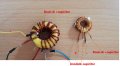
I tried the circuit with two separate cores, I wound the big core myself and bought the other one ready-made, and in both cases it was exactly the same problem.
Both cores had two coils
I will report the exact value of both as soon as the LCR meter arrives
Thankful
 

Ian0

Joined Aug 7, 2020
9,847
Look at the waveform across R10. The slope should be constant - it should be a nice triangular shape (it will have a bit of a spike at the beginning). If it curves upwards the core is saturating.
If you measure the slope you can work out the inductance, because V/L = dI/dt
 

Thread Starter

mrh586

Joined Dec 5, 2021
90
If your input voltage is 30V, then why would you want to step the voltage UP for the motor?
If you buy a motor with a rated voltage lower than the power supply, then you would only ever have to step down, and you could use a standard buck converter; or, as it appears to be a brushed DC motor, you could driver it directly with PWM and not need any inductors
No, I don't want this converter for the motor
But for the test, I didn't have anything other than the motor available
 
Last edited:

ronsimpson

Joined Oct 7, 2019
3,052
When I try with a normal DC motor, it works with a slight voltage drop compared to no load
But when I try a 775 model motor, the motor turns on for a moment and then turns off, and the voltage becomes zero and the MOSFET heats up,
There are many different vendors making the 775. It appears to be a 12V motor that can run from 12 to 24. Some say down to 6V and some say as high as 36V. Sever places say it takes 10A to start the motor. It should not be used above 150 watts.

In the first posts it looks like you had 12V and wanted to boost to 24V. Now it is clear you have 30V and only want to drop the voltage. Several of us don't see the need for a buck/boost. A buck will use less parts.
 

Thread Starter

mrh586

Joined Dec 5, 2021
90
There are many different vendors making the 775. It appears to be a 12V motor that can run from 12 to 24. Some say down to 6V and some say as high as 36V. Sever places say it takes 10A to start the motor. It should not be used above 150 watts.

In the first posts it looks like you had 12V and wanted to boost to 24V. Now it is clear you have 30V and only want to drop the voltage. Several of us don't see the need for a buck/boost. A buck will use less parts.
As I explained in a previous post, I don't want this circuit for a DC motor
Just for testing, I didn't have any other equipment
By the way, I am going to get a lamp for testing
Do you know any special equipment for current testing?
 

Ian0

Joined Aug 7, 2020
9,847
That would depend on how much power your design produces.
If you work out your load resistance, the get five resistors (because they are often sold in packs of 5) each of 5 times the resistance and a fifth of the power the you can load test at 20%, 40%, 60%, 80% and full load.
 

Thread Starter

mrh586

Joined Dec 5, 2021
90
You haven't specified the output power, but 500uH is probably more like what you need.
What is the method of calculating the amount of inductance required for this circuit?
Does it have a special formula?
How is the capacity of capacitors determined?
Thanks for your tips
 

Thread Starter

mrh586

Joined Dec 5, 2021
90
That's Micrometals #26, or a copy thereof. It's iron powder, not ferrite, and it is exactly what you need for a SEPIC converter. From your previous posts, if it is 40mm outside diameter than it is a T157-26
I also have another core which looks like the picture below
OD = 38.5, ID = 21 and its height is 17 mm
But no matter how hard I tried, I could not find its specifications
Maybe this core needs less winding
 

Attachments

Ian0

Joined Aug 7, 2020
9,847
I also have another kernel which looks like the picture below
OD = 38.5, ID = 21 and its height is 17 mm
But no matter how hard I tried, I could not find its specifications
Maybe this core needs less winding
Looks like ferrite to me - won't work in that circuit without a gap.
 

Ian0

Joined Aug 7, 2020
9,847
What is the method of calculating the amount of inductance required for this circuit?
Does it have a special formula?
How is the capacity of capacitors determined?
Thanks for your tips
All switched-mode circuits are governed by V/L=dI/dt (or ΔI/Δt). You have to determine which t, which I and which V.
It gets more complicated with two windings on the same core, but start by deciding how much current ripple you can accept, say 10% the total current. That's your value for ΔI. Assume a 50% mark space ratio, so Δt=1/(2f)
V is the voltage across the inductor - that's your power supply voltage.
As you can tell from "first choose your ripple current" it's not an exact science, and a range of values will work. More inductance = more winding loss, less inductance = more core loss and more ripple.
 

Thread Starter

mrh586

Joined Dec 5, 2021
90
All switched-mode circuits are governed by V/L=dI/dt (or ΔI/Δt). You have to determine which t, which I and which V.
It gets more complicated with two windings on the same core, but start by deciding how much current ripple you can accept, say 10% the total current. That's your value for ΔI. Assume a 50% mark space ratio, so Δt=1/(2f)
V is the voltage across the inductor - that's your power supply voltage.
As you can tell from "first choose your ripple current" it's not an exact science, and a range of values will work. More inductance = more winding loss, less inductance = more core loss and more ripple.
my God
It became very specialized
I saw a clip on YouTube that built and tested the same circuit with the same number of coil turns and a yellow and white core (like what I have), just smaller.
I just made the core a little bigger
I'm surprised it doesn't work
 

Ian0

Joined Aug 7, 2020
9,847
my God
It became very specialized
I saw a clip on YouTube that built and tested the same circuit with the same number of coil turns and a yellow and white core (like what I have), just smaller.
I just made the core a little bigger
I'm surprised it doesn't work
Did you get the two windings correctly phased?
The Micrometals #26 will take a lot of magnetomotive force to saturate, but it will suffer from high core losses with large flux excursions.
 

Thread Starter

mrh586

Joined Dec 5, 2021
90
Did you get the two windings correctly phased?
I do not know
I tried to connect the phases according to the clip
In one of the posts, I mentioned that if there is a link or an article about how to connect the phases, please introduce it.
I gave negative and positive to the two primary wires, and on the secondary side, I connected the drain to the positive and the anode to the negative.
 

Ian0

Joined Aug 7, 2020
9,847
Čuk converters benefit from separated windings (each covering 180°) - you can do clever stuff like ripple current steering. I've never thought about whether SEPICs also do - they might, because they work perfectly well with two separate inductors.
 

Thread Starter

mrh586

Joined Dec 5, 2021
90
Čuk converters benefit from separated windings (each covering 180°) - you can do clever stuff like ripple current steering. I've never thought about whether SEPICs also do - they might, because they work perfectly well with two separate inductors.
These are the transformers I tested the circuit with
 

Attachments

Top