Types of Class B Amplifers and Current Use

Audioguru again

Joined Oct 21, 2019
6,826
The impedance of the electromagnet, the frequency and voltage levels to it determine if the amplifier survives or instead lets out the magic smoke.

Why would seeds sense a magnetic field? Did they receive the Covid-19 vaccine and wrongly believe it makes them magnetic??
EDIT: The scientists say the germination rate of the plants was 20% higher when the frequency was 10Hz. But in the end of the article they imply that a static (?) magnetic field was 20% better than a pulsed magnetic field. They are confusing.
 
Last edited:

Thread Starter

Sir Kit

Joined Feb 29, 2012
213
Yes, there is ongoing research in this area. In general, biology is more susceptible to pulsed stimulation (insert crude mental image of your choice). Same applies to driving a nail.

It appears that the two solutions offered so far would alter frequency and waveform. The setup on page 6 in the following article is an alternative without this drawback. https://www.etesttool.com/downloads/pdf/Keysight/Keysight-33502A/5992-3310EN.pdf

But I am not sure where to find an off-the-shelf 500:1 transformer, or how much a 1 turn winding is going to "modulate" the DC supply's current in real life.

Any other ideas or comments would be appreciated.
 

Audioguru again

Joined Oct 21, 2019
6,826
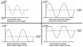
Any audio amplifier can have a DC offset at its input without using a transformer. But then the center voltage of the sinewave will have the offset voltage, not the lowest voltage of the waveform. Then when the input level is changed, the DC offset voltage must also be changed to match it.
I sketched what I think you want and what will happen if the level and offset voltages are not adjusted so they match:
 

Attachments

Danko

Joined Nov 22, 2017
2,199
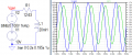
A. In experiment, value of magnetic field amplitude should be permanent, independent from frequency.
Therefore, circuit should contain feedback, which changes amplitude of sine (Vsine), when intended current amplitude (Icoil) trying to change.
B. Offset voltage Voff = 0.5 * Icoil * Rcoil
In circuit below V1=10V is offset voltage, R1=12.63Ω is coil resistance.
1636577484583.png
 

Attachments

Last edited:

Thread Starter

Sir Kit

Joined Feb 29, 2012
213
If you want a sinewave plus a DC offset, the simple solution is to use an op-amp.
This would require a circuit build to replicate. Beyond the skills of cohorts.

I did consider using a separately powered emitter follower at the hi-fi amp's output. It seems a bit redundant though, and dismissed for the same reason as above.
 

Danko

Joined Nov 22, 2017
2,199
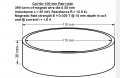
Isn't the value of L1 frequency dependent? Depending upon inductors at hand, this could limit the scope of experimentation.
Inductance of coil L1 and resistance R1 of coil are not dependent on frequency.
But current through L1 and magnetic field are dependent.
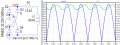
Here is used one coil. But value of Vsine should be manually or automatically adjusted at every change of frequency.
ADDED:
1636609922998.png
 
Last edited:

Thread Starter

Sir Kit

Joined Feb 29, 2012
213
Any audio amplifier can have a DC offset at its input without using a transformer. But then the center voltage of the sinewave will have the offset voltage, not the lowest voltage of the waveform. Then when the input level is changed, the DC offset voltage must also be changed to match it.
I sketched what I think you want and what will happen if the level and offset voltages are not adjusted so they match:
Would this still hold true if the amp input is capacitively coupled at both ends?

Take the example of a computer sound card outputting a sine wave, to which a 5V+ offset has been applied in software. What happens when that signal is fed into a hi-fi amp? What does the amp's output look like?
 

Audioguru again

Joined Oct 21, 2019
6,826
Would this still hold true if the amp input is capacitively coupled at both ends?

Take the example of a computer sound card outputting a sine wave, to which a 5V+ offset has been applied in software. What happens when that signal is fed into a hi-fi amp? What does the amp's output look like?
The input and output capacitors in an amplifier block DC but pass AC. AC alternates positive voltage, then negative voltage, then positive voltage again, then negative voltage again over and over.
You can feed a DC offset voltage to the input of an amplifier if you remove its input capacitor and remove its output capacitor to get the output offset voltages I showed. The average center voltage is offset, you need to fiddle with adjustments to make the offset voltage at 0VDC. It will be much easier if the seeds respond to squarewave pulses instead of sinewaves.
 

Thread Starter

Sir Kit

Joined Feb 29, 2012
213
Thanks to all for clarifying those points. I have shorted over blocking caps before. The amp then operates like class A. Runs "warm" and wattage needs to be down-rated accordingly.

But, as per my OP, I was hoping to enlist a stock amp without internal mods.

How about a PA line matching transformer across the amp's output with its secondary in series with the load and a power supply set at half signal volts out to provide the DC offset? So far, I cannot think of anything simpler. Also, if the offset is accidentally set too high, any continuous current then comes from the supply and not the amp. Please correct me if I am wrong.

Suggestions?
 

BobTPH

Joined Jun 5, 2013
11,585
And you have totally ignored the simplest solution proposed in my post #18. All you need is a typical wall wart.

Bob
 

Audioguru again

Joined Oct 21, 2019
6,826
A class-A amplifier gets very hot all the time even when it has no output signal.
A class-AB amplifier produces about half as much heating power as its actual output power which is very low heating when it has no output signal.

An audio amplifier is designed to drive a speaker, and some amplifiers might not properly drive a transformer and might be damaged if you add an offset voltage to the amplifier's output.
 

Thread Starter

Sir Kit

Joined Feb 29, 2012
213
If you add a DC voltage to the output of most audio amplifiers then its large output capacitor will be reverse biased causing an explosion!
That's one reason why, in post #33, I proposed using the PA output transformer. The primary is typically impedance matched for audio amps. I would use the 8R tap. Output is about 100Vpp, which is no problem for the magnetic coil itself. I just need to add a load resistor, say 400R for a 25W amp, so as not to exceed the amp's rating. Good idea or not?

I reviewed the suggestion in post #17, but it seems to have the disadvantage of changing the waveform. Range of frequencies would ideally be sub-audio to 10KHz, to provide scope for exps.
 

Audioguru again

Joined Oct 21, 2019
6,826
PA speaker transformers are 70.7V RMS in North America which is 200Vp-p.
70.7V at 25W is a 200 ohms impedance that your magnetic coil must produce at your frequency (10Hz?).
The coil is the load, where and why add a 400 ohms resistor?
Many PA transformers do not pass frequencies below 100Hz.
 
Top