 Facebook
 Google
 GitHub
 Linkedin
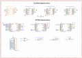
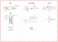
Please take a look at the sensor board, the upper part is made of FPC (two-layer board), and the lower part is the data acquisition hard board (two-layer board).
Description of the problem: The board reserved an LED without welding. The iic communication and serial communication of the sensor are normal when the sensor is powered on for the first time. After the LED is welded, it can be used normally for the first time, but the AMS1117-3.3 chip is very hot, and the LED is not bright when it is powered on again, the iic address scan is missing, and the serial port cannot be connected. The output voltage of AMS1117-3.3 is normal when measured with a multimeter.
Description of the problem: The board reserved an LED without welding. The iic communication and serial communication of the sensor are normal when the sensor is powered on for the first time. After the LED is welded, it can be used normally for the first time, but the AMS1117-3.3 chip is very hot, and the LED is not bright when it is powered on again, the iic address scan is missing, and the serial port cannot be connected. The output voltage of AMS1117-3.3 is normal when measured with a multimeter.
Attachments
-
 199.4 KB Views: 7
 -
 153.3 KB Views: 7


