Trying to fix a Marantz PM 35 amplfier

Thread Starter

Yami

Joined Jan 18, 2016
354
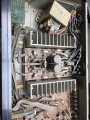
Hi, I’ve got a Marantz PM 35 amplifier which I’m trying to restore. It was in real bad condition when I got it full of dust, and there was no output. Cleaned the whole thing touched up the dry joints. It looks like some else has gone in before me as I can see lifted pcb traces which has been fixed and some parts are filled with dried up solder flux. I wasn’t able to get a service manual for it however I was able to find a detailed schematic which was very accurate except for some componet values. It is at http://akdatabase.org/AKview/albums/userpics/10007/Marantz PM-35 Schematic.pdf

Anyway here is what I have done so far.

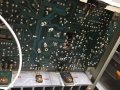
1. Touched up all the dry joints that I could find (feels like I have re soldered the whole board back again).

2. Changed the 24V regulator.

3. Changed some leaky electrolytic capacitors.

4. All the output transistors and everything seemed to be in working order meaning couldn’t find any shorts etc.


The problem

The audio output is distorted on the left and right channel. Same for the speaker and headphones.


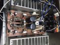
Voltage measured across components/test points seems ok relative to the schematic nothing too out of the ordinary. But I am not able to get 35V at the main bridge rectifier output. It only went upto 25V! Normally it’s even below that around 20V. This is what I have found so far – It goes upto 25V when one side of the amplifier was not turning on (left output side). I measured 300mV at (Q711) which is half of what it should be. When it rises up to 600mV the output of the rectifier goes down to 20V. I touched up the solder joints of the amplifier IC (uPC1270H) and now I get steady voltage of 600mV at the base of Q711. But now I get 20V at the bridge rectifier.

Following this I get 18V at the input of the 24V regulator! And only have 16V at the output of the regulator :S. I didn’t measure 24V at the output of the regulator at any instance the highest it went was around 20V.

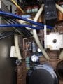
Another thing I remarked was R805 which is a safety resistor gets quite hot and it has got burn mark. It checks out ok I have checked after it and before it but couldn’t find any shorts. I measured 10V across it which seems reasonable, its well within the power rating of the resistor.

When I first powered it on the speaker protection relay didn’t engage, but now after all the work done the relay turns on but it takes quite a significant time to turn on.

I am using the series light bulb trick - the light bulb turns on briefly when the amp is turned on but remains off afterwards.

I would really like to get this to work please advice on what else to do and other test I could do.


Thanks so much for the help.
 

Attachments

AlbertHall

Joined Jun 4, 2014
12,619
You need to know whether the voltages are low because of a fault or because of the light bulb reducing the supply voltage.
Try it without the bulb. Measure the two rectifier (D801) outputs, or the voltages across C801 and C802 if that's easier to get to.
 

Thread Starter

Yami

Joined Jan 18, 2016
354
Hi guys, some new updates. I touched up some more joints and removed both the VRs which is used to set the bias for Q703 and Q704 cleaned them and put them back in. Turned the power on with the light bulb in series. The light bulb had a faint glow, changed the bulb to a higher power bulb and it also had a faint glow (I didn't get that before). After that I removed the bulb and powered up the amp directly. Nothing blew! :D
Anyway still I get a voltage reading of 22V at the main rectifier output.

Somethings I found out:
1.The two main filter caps had a hard time holding a consistent voltage across them.
2.Still the 24V regulator input reads 18V and the output reads 16V.
3.The heat sink on one side got really HOT (it has got Q712, Q710, Q704). The other heat sink remained 'coldish'
4. Some of the voltages at the pins of the amplifier IC was a bit off probably due to bias being a bit off.
5. The protective relay turned on a little bit faster than before, but as I turned off the amp and turned it back on again the realy took some time to engage.

I feel that the biggest clue is the delay in the protective relay turning on.

What could be the possible issues I could look for? Unfortunately I don't have a bench power supply :( ....

Further questions
1. How can I check whether amplifier IC is not faulty. I might be able to get one spare IC but I'm afraid that by changing it I could damage the one spare I have.
2. The TA7317P IC is also a mystery to me. How can I check whether its faulty.
3. Would an analog multimeter be good to measure voltages across caps - suppose to be more responsive right? Generally I thought that jumping voltage across caps indicated either a leaky cap or some other issue with the components close to it.

The main reason to trying restore this amp is mainly for emotional reason rather than for its fidelity :)
Hope you guys could help me out
Thanks
 

AlbertHall

Joined Jun 4, 2014
12,619
The two pots which you removed and cleaned set up the standing current through the output transistors so if one side is getting hot and one isn't it might be because those pots aren't set correctly.
Do you have the procedure for setting them correctly?
 

Thread Starter

Yami

Joined Jan 18, 2016
354
The two pots which you removed and cleaned set up the standing current through the output transistors so if one side is getting hot and one isn't it might be because those pots aren't set correctly.
Do you have the procedure for setting them correctly?
Unfortunately not, I wasn't able to find a service manual :( . But what I did was I got both of the voltage at the bases of Q704 and Q703 to match. The only solution I could think of. However it didn't have any effect on the temperature on either sides.

I think that its suppose to get that hot by looking at the size of the heat sinks. I guess the issue should be on the cold side.

I forgot to mention about the audio quality too - The quality seems a bit better now on one output - the side which gets hot, but still its distorted.
 

AlbertHall

Joined Jun 4, 2014
12,619
Try adjusting R719 to get 10mV across R731, and R720 to get 10mV across R734.
I mean between the ends of each resistor not from the resistor to ground.
 

Thread Starter

Yami

Joined Jan 18, 2016
354
I have adjusted the variable resistors so that across R734 and R733 its now 10mV. I had some trouble getting 10mV across R733 (right channel). I flipped the µPC1270H of that channel and was able to adjust the voltage. I would like to ask why 10mV - 20mV though?

Still the main output of the rectifier remained at ~24V but it did go upto 25 volts at one point but is steady at 24.xxV.

I monitored the 2nd pin of TA7317 during power on. The relay engages only when the voltage of that pin goes to -8mV. I found that once the power is on the voltage at that pin is about 47mV and takes quite a significant delay to go down to -8mV. I did change the CN02 capacitor hoping that it was the issue, but there was no difference.

Regarding the 24V regulator - C805 capacitor was burned when I first opened the unit. I removed it to find that it was 22uF but the schematic had a 47uF capacitor so I changed it to a 47uF cap. Could this be an issue?

Still the audio output is distorted. I played through some sine waves and clearly I can hear the distortion sounds like a square waves
 

Thread Starter

Yami

Joined Jan 18, 2016
354
By flipped I meant I replaced the IC with a new IC. Yep both channel sounds similar but I feel the left channel is slightly better. I didn't measure R733 and R734 to ground. I'll check it out and let you know.
Nothing getting really HOT now but slightly warm.

Thanks
 

Ylli

Joined Nov 13, 2015
1,092
You cannot rely on the AC ranges on a multimeter being capacitor coupled so this test is likely to give misleading results.
Was looking AC output of the transformer. Would not expect any DC there, so whether the meter was AC or DC coupled would be immaterial. I asked for both AC and DC voltage at the CT just to be sure that was properly connected to the chassis for further measurements.

But I removed my post, because after re-reading the entire text, you are doing a fine job of walking him though it, and I didn't want to confuse things.
 

Thread Starter

Yami

Joined Jan 18, 2016
354
Some updates:
I measured the voltage at R733 and R734 to ground and it measures -0.011V and -0.013V (why do I get a minus voltage here)

Some more findings
I had a look at the other boards like PV01 to find out if anything was shorting out - as this could bring down the 24V output. I couldn't find anything but what I noticed that voltages are slightly off but very close to the marked values of the schematic. But what stood out was at Q405 pin 1 schematic says -25mV but I measure -47mV close to double.
Also with the other boards the ground relative to chassis ground is also a bit off, I connected alligator clips to make the chassis connection the same but still the ground voltages were off by couple of volts. (its a little of a concern right?)
I removed the bridge rectifier to clean it up etc. decided to power on the amp without it - I noticed that at diode D802 it measures 18V (looks correct as the transformer out is around 19V) which goes to pin 1 of the voltage regulator, I found this a bit interesting too - if the main rectifier is in I would get 20V. Whats happening here :S.
Another alarming point - I measured the voltage of negative pin of C805 and it kept jumping around.
and finally could you help me figure out what this part of the circuit does -

Photo 1.jpg

Thanks a million
 

AlbertHall

Joined Jun 4, 2014
12,619
So the output voltages are close to zero as they should be. The amplifier has positive and negative supplies and is trying to keep the output near zero, but it is always going to be just a little positive or negative. Yours happens to be negative but that's OK.

The circuit you show is a ±15V regulated power supply.

Now, with no input signal and the volume turned up, balance in the middle, what do you hear? Do both channels sound about the same?
 

Thread Starter

Yami

Joined Jan 18, 2016
354
Just an update
I had a potential breakthrough - I was playing music through my phone and was using the phono input of the amp. I had to bring down the output of the phone way down and I was able to get audio output with out any distortion. It was working ok-ish. So I was hoping that I was heading in the right direction.
So I thought I will put back the amp as the boards were all over the place. So I put the amp back together not all the way but tidied up a bit. I turned the amp back on and the relay didn't click :(
I checked voltages at TA7317P pins, the voltages seemed to be in order apart from the pin going to the relay. Then I thought it must be the TA731P IC so I replaced it with a new one. No luck checked the voltages again and now I measure -0.900V at pin 2 and its suppose to measure -9.9mV! The biasing voltages of the transistors also are in order.
I have gone further back then when I started :'(
 
Top