Trying to make a moped ignition coil tester

Thread Starter

fredy mredy

Joined Jul 5, 2019
22
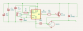
Ive tried to reverse engineer a circuit board for coil ignition testing but it was covered mostly in glue and i could not see all the paths on the board.
1000015932.jpg1000015933.jpg
then i tried asking google AI to recreate the circuit from the drawings ive made. (i tried to make it in KiCad)
circ.pngcirc1.png
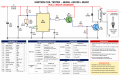
And i asked ChatGPT for help and made this Circuit(s)
ChatGPT Image May 20, 2026, 02_10_19 AM.pngChatGPT Image May 20, 2026, 02_10_00 AM.pngI noticed that Chatgpt connected the 2nd pin from the potentiometer (wiper) to nothing. (made more mistakes as i asked to fix something)
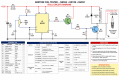
i got BD139 instead of BC286 because i could not find it for sale, also the BU931ZP i got BU931P.
Is it possible to make it simpler and working?
 

Attachments

crutschow

Joined Mar 14, 2008
38,537
Yes, diode D1 will short-circuit all the inductive coil energy and totally kill the output spark.

AI strikes again. :rolleyes:
It looks like we will be spending more and more time on this forum just correcting AI generated errors in circuits posted by newbies.
 
Last edited:
It's double the work- correcting AI circuits and the requirements when OP has no access or budget for some of the semiconductors: BU931 is overkill 400V 15A TO-3 and obsolete. It's a power Darlington so the extra drive transistor is not needed. The industry moved to ignition IGBT's long ago.

AI is just kludging together and copying graphics from schematics to make a mess.
Reply #2 circuit is missing a resistor to limit base-drive to Q3, and has no oscillator either. 100nF across the transistor is too big.

I just put a 555 on a breadboard and had fun making big arcs from a coil when I was a kid. Then I got a scope and refined it when I was older. Learned the craft from scratch.
Those days are long gone, so I guess it's up to people on forums to correct AI mishmash?
 

panic mode

Joined Oct 10, 2011
5,017
aw c'mon... AI is still in infancy. it will take some time but AI will get better and better... same was with radio, TV, computers or any new technology. and the only way to make it better is to use it.
 
Last edited:

Thread Starter

fredy mredy

Joined Jul 5, 2019
22
Take out diode, connected parallel to coil, else you never will get spark.
Look at this schematic:
https://www.researchgate.net/figure...cal-circuit-b-Ignition-circuit_fig4_263957362
View attachment 367442
If i take the diode, the ignition coil should be connected directly to the BU931 Collector?
circ1.png

Yes, diode D1 will short-circuit all the inductive coil energy and totally kill the output spark.

AI strikes again. :rolleyes:
It looks like we will be spending more and more time on this forum just correcting AI generated errors in circuits posted by newbies.
As someone as me who has not enough experience its quite helpful. I need this tester so i can test bunch of my coils to see which ones are good and which ones have to go to bin.
 
AI can't do electronic circuit design. People keep saying it will get better- it's what everyone wants but does not have. Helping noobs "punch above their weight class" - they don't actually learn anything. Here are the answers to the math exam. Did you learn math? No.
Until then, there are no rewards for the humans cleaning up machine generated slop.
It's hard enough without information on requirements and parts used etc.

"Ignition coil driver" circuits are hilarious, copied by bloggers for decades now. So many circuits on the Internet are wrong or even stupid. Then AI copies these and rolls with 'em, and here we are.

If the TS could let us know what parts are available, what a "tomas ignition coil" means, are these mopeds CDI? Is this 6V or 12V? Could offer some suggestions.
 

Thread Starter

fredy mredy

Joined Jul 5, 2019
22
AI can't do electronic circuit design. People keep saying it will get better- it's what everyone wants but does not have. Helping noobs "punch above their weight class" - they don't actually learn anything. Here are the answers to the math exam. Did you learn math? No.
Until then, there are no rewards for the humans cleaning up machine generated slop.
It's hard enough without information on requirements and parts used etc.

"Ignition coil driver" circuits are hilarious, copied by bloggers for decades now. So many circuits on the Internet are wrong or even stupid. Then AI copies these and rolls with 'em, and here we are.

If the TS could let us know what parts are available, what a "tomas ignition coil" means, are these mopeds CDI? Is this 6V or 12V? Could offer some suggestions.
I already bought the BU931P, NE555, BD139. I didnt bought the Diode UF4007 it was out of stock. I have resistors and capacitors. If i need anything else i can buy it. if you can make better circuit diagram than this will be much helpful.

Tomos is a moped brand. The ignition coils are not CDI. Most of them are 6V, but there are also 12V.
Tomos-ignition-coil-6-Volt-12v.jpg
Here is an image to see it how it looks., the white wire is connected to the capacitor and point. The black middle pin is where the cable for the sparkplug goes.
paint ign coil.png(I did it in paint xD)
There are CDI ignition coils for mopeds (no points or capacitors) but this tester will not work for them i think. (img bellow)
3392_1.jpg
 
Last edited:

Thread Starter

fredy mredy

Joined Jul 5, 2019
22
I already bought the BU931P, NE555, BD139. I didnt bought the Diode UF4007 it was out of stock. I have resistors and capacitors. If i need anything else i can buy it. if you can make better circuit diagram than this will be much helpful.

Tomos is a moped brand. The ignition coils are not CDI. Most of them are 6V, but there are also 12V.
View attachment 367477
Here is an image to see it how it looks., the white wire is connected to the capacitor and point. The black middle pin is where the cable for the sparkplug goes.
View attachment 367478(I did it in paint xD)
There are CDI ignition coils for mopeds (no points or capacitors) but this tester will not work for them i think. (img bellow)
View attachment 367479
 

crutschow

Joined Mar 14, 2008
38,537
If i take the diode, the ignition coil should be connected directly to the BU931 Collector?
Yes.
But the transistor needs overvoltage protection (particularly when the secondary has no load) so you need Zener(s) with a voltage rating lower than the transistor's max collector-emitter rating, from its collector to base as shown in Post #2.
 

Thread Starter

fredy mredy

Joined Jul 5, 2019
22
Yes.
But the transistor needs overvoltage protection (particularly when the secondary has no load) so you need Zener(s) with a voltage rating lower than the transistor's max collector-emitter rating, from its collector to base as shown in Post #2.
I will try to re-make the circuit design after i get home and i will reply it to you.
 
Top