Trying to find PWM terminology/equation for DC/DC conversion.

Thread Starter

farm_tinker

Joined Nov 20, 2025
18
I'm playing with a microcontroller and SMPS desgin. (synchronus inverting buckboost topology.)

Usually, when I have a electronics or programming idea/problem, someone figured it out decades ago and I just need to know what it's called to find all sorts of info. I've done a fair amount of searching on these questions but either I'm not using the right terms or I'm overlooking something.

I can generate a 625kHz pwm signal. However, my period is only 32 bits wide at that speed. I.E., I have a resolution of 32 bits instead of 256 or more.

Is there a term or rule of thumb for the minimum resolution needed for regulating a switch mode supply? Maybe a paper or application note? Something I can do some reading on.

I've got an idea for a two stage adjustment of the duty cycle. A window comparator/ADC signals an out of bounds condition. Using programable fast logic I can initially offset the duty cycle by some amount larger or smaller in less than a single clock cycle. At the same time, an interrupt is generated and the CPU starts cranking away at resetting the timers precisely.

Is there a term or technique for an automatic fast coarse adjustment to pwm duty followed by a precision adjustment?

Any help/advice/commentary is greatly appreciated!
 

MisterBill2

Joined Jan 23, 2018
27,888
I am not aware of a software REGULATED power supply, but I have seen software CONTROLLED power supplies. And certainly setting the voltage with software, either a D/A scheme or even a PWM scheme seems reasonable.
 

BobTPH

Joined Jun 5, 2013
11,599
I am not aware of a software REGULATED power supply, but I have seen software CONTROLLED power supplies. And certainly setting the voltage with software, either a D/A scheme or even a PWM scheme seems reasonable.
I made one as my first microcontroller project, a smart charger for my drill/driver battery (NiMH.) To get good enough resolution, I used a calculated jump into a table of NOPs to set the period with 1 instruction cycle resolution. This was on a low end PIC micro.
 

Thread Starter

farm_tinker

Joined Nov 20, 2025
18
Minimum efficient pwm pulse length is turning up the sorts of discussions and resources that may lead to what I'm looking for. Thank you!

Burst packet turns up pulse density modulation. (Which I'm understanding as similar to skip mode.) Both have some overlap to what I'm thinking of by using logic to alter the the duty. It may put me on the right track. Thank you again!

At minimum, I've got some leads.
 

kiroma

Joined Apr 30, 2014
119
I don't know very much about the topic, just read because it interests me, and couldn't not comment that by "32 bits" you meant 32 values. It's 5 bits. Anything past 20 bits or so is too much for the majority of applications. But yes, I know that in a timer you can only trade resolution by faster cycles, because there's a fixed frequency of clock to it.
 

ronsimpson

Joined Oct 7, 2019
4,755
I can generate a 625kHz pwm signal. However, my period is only 32 bits wide at that speed. I.E., I have a resolution of 32 bits instead of 256 or more.
I don't know your computer but:
At high frequencies "625kHz pwm" most computers have low resolution. My guess is "32 bits wide" is really 5 bits giving you 32 steps. Very likely at 315.5khz you have 64 possible steps. At 160khz you have 128 steps and at 80khz you have 8 bit of control. If I am right, you are using a 20mhz clock to set the pwm in your computer.

If you really only have 32 choices of value to put into the pwm, then there are several options.
---One is to slow down the pwm to get more bits. You can only make changes at 20mhz speed. (50nS)
---Another option; lets say loading the pwm with 15 is not right but 14 is not right either. You can load the pwm like this (15, 14, 15, 14) to get 14.5. or you can (15, 14, 14, 14,) and you will get 14.25. I have made tables of numbers that get loaded into the pwm. (15,14,14,14,15,14,14,14,15.......) Four more bits will give you 16 choices between every one of the 32 choices you now have. (32x126)

There are other games that can be played. I have done this many times.
 

Thread Starter

farm_tinker

Joined Nov 20, 2025
18
---Another option; lets say loading the pwm with 15 is not right but 14 is not right either. You can load the pwm like this (15, 14, 15, 14) to get 14.5.
Does that method have a formal name that you know of? Any chance you could point me at books/papers/pages that cover this sort of thing?

@kiroma @ronsimpson Regarding '32 bits.' You're both correct. At 625kHz I have a resolution of 32. My system clock is 20mHz, I'm playing with an ATtiny 3224. While the registers controlling my pulse are 16 or 8 bits (depends on timer settings), I only have time for 32 values. Not sure if 'value' is the correct term. If this was X and Y, it would be pixels, for instance.
 

ronsimpson

Joined Oct 7, 2019
4,755
I only have time for 32 values.
32 values come from 5 bits.
Why 625khz. Are you trying to keep the inductor small? You might want to run at 80khz to get 8 bit 256 levels.

I think you are using an ADC to read the output voltage. I assume you have good resolution there. With a closed loop system, the pwm will find the right value(s). Let say you have 32 possible values. Likely 0% and 100% will not work in you type of supply. Probably values 0,1,2,3 will not work and values of 30,31,32 will not work. Using my example from before you need a value of 14.5 but you can't make that because of the counter in the computer. What will happen is that the "software error amplifier" will demand 14 for (maybe 5 cycles) then demand 15 for (maybe 5 cycles). This will give you the 14.5 you need. I will say it a different way. It will take time for the error amp to realize that 14 is too low, and it will take time to understand that 15 is too high. So the close loop will bounce between the two values.
 

Thread Starter

farm_tinker

Joined Nov 20, 2025
18
I double checked my reference circuit. My target is 125kHz. My load is 14.5w and is a dumb resistive heating element at 1.6ohms. So, around 4V and 3A from a single cell lithium, call it 3.7V nominal supply.

Given that the load doesn't care how ugly the power it gets is, I can have a ton of noise in the power as long as I don't start interfering with pacemakers and cellphones. That's also why I'm going for the inverting buckboost, a heater doesn't care about negative voltage.

I could actually probably get a driver IC that will do all this for me. However, I'm using it as an opportunity to learn about: SMPS, my new RIGOL DS1202Z-E scope, and the newer AVR microcontrollers.

I've been fooling around with Texas Instruments Power Stage designer. My reference circuit has a 1.5uH inductor and Power Stage is recommending around 400kHz for that inductance. Reference seems to have 4 mosfets, so some sort of full bridge. All the ICs have been laser obfuscated.

I picked 625kHz because that was about as fast as I figured I could get a useful signal. I probably won't end up there, but you learn a lot on the edges. Everything has switch mode power in it now, even my arc welder. When it has a problem, you chunk the entire machine or appliance because a replacement control board costs as much as a new one. Switch mode power seems to be a black box for most people and I want to understand it better.
 

ronsimpson

Joined Oct 7, 2019
4,755
Reference seems to have 4 mosfets, so some sort of full bridge.
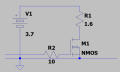
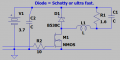
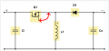
Full bridge is too complicated. In the simplest form just send square waves to the resistive load. It may make too much RF noise, but it will work.
1784765421340.png
In this example there is a low pass filter to remove the high frequencies from the wire to the load. The diode should be a Schottky or ultra-fast.
1784765851439.png
 

Thread Starter

farm_tinker

Joined Nov 20, 2025
18
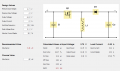
This is an approximation of what I'll likely end up with. The diode replaced with a MOSFET for synchronous operation, need to do some more reading to understand what the voltage drop of a MOSFET should be in this circuit.

Screenshot 2026-07-23 054511.png


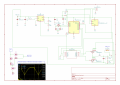
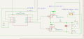
This is the current state of the design. My apologies. It's messy, incomplete, and probably not very legible. (I'm more at the module testing stage for both hardware and software.)
boost_box_0.1.png

Detail of synchronous inverting buckboost. R7/R8 are the voltage divider for feedback; as drawn, they would deliver a negative voltage that might fry the microcontroller and isn't a usable signal. U4 is a FAN32224 gate driver IC capable of several amps at 5V for crisp switching of the MOSFETs. MOSFETs are logic level Toshiba SSM6K804R. L2 1.5uH inductor will likely change to 6uH or so, even the 6uH inductor I'm looking at is capable of 11.5A.

Screenshot 2026-07-23 061615.png
 

BobTPH

Joined Jun 5, 2013
11,599
Why are you going you going to so much trouble for a heating element? A low frequency PWM is all you need. Start with a voltage high enough to achieve the max power needed, then cut the power down with PWM at say 1KHz. If you need a higher voltage than your supply, just use an off the shelf boost regulator to feed the PWM circuit.
 

ronsimpson

Joined Oct 7, 2019
4,755
When driving a MOSFET's gate, it does not care what the Gate to Ground voltage is. It only cares what the Gate to Source voltage is.

In your example the Gate signal is not referenced to Ground but to the Source of the MOSFET. In this circuit, when the MOSFET is on the Source is almost at the input voltage so the Gate needs to be 5V above the input voltage. When the MOSFET is off the Source is about the output voltage (-4.8V). The Gate drive needs about +10V to -6V to work and your gate driver cannot do that easily.
1784818000464.png
 

ronsimpson

Joined Oct 7, 2019
4,755
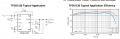
Here is a Boost Up PWM that might work. It probably needs to be a little higher current. It boosts your battery voltage up to 4.8V at 3A. It can't do 3A at low battery voltage. Something to think about. The point here is to use a PWM, not make your own.
1784819189047.png
I need to look into this more. If you pull EN low the output voltage drops to (either 0V or Vin I don't know which).
 

ronsimpson

Joined Oct 7, 2019
4,755
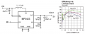
Here is another example. The data sheet; under "EN" said that the load is isolated from the input voltage when EN=off. So I think the output voltage will be 0V when disabled.
1784819940997.png
----edited----
If you want to adjust the current or voltage to the heater, you have options. One is to change R1, R2 and there are many ways to do that from the computer. Another way is to "PWM" the EN pin at some slow frequency like 400hz. The heater will be just fine with 400hz PWM. If you drive the EN pin at 50% PWM at some slow frequency the heater will get current 1/2 of the time.
 
Last edited:

drjohsmith

Joined Dec 13, 2021
1,629
Does that method have a formal name that you know of? Any chance you could point me at books/papers/pages that cover this sort of thing?

@kiroma @ronsimpson Regarding '32 bits.' You're both correct. At 625kHz I have a resolution of 32. My system clock is 20mHz, I'm playing with an ATtiny 3224. While the registers controlling my pulse are 16 or 8 bits (depends on timer settings), I only have time for 32 values. Not sure if 'value' is the correct term. If this was X and Y, it would be pixels, for instance.
The method Is dithering or pulse swallowing depending upon application .
 

Thread Starter

farm_tinker

Joined Nov 20, 2025
18
Why are you going you going to so much trouble for a heating element?
Stubbornness? Maybe a little bit of Old Man and the Sea? Not sure what the rules are, but I want to ultimately build my own version of an obsolete ecig. (Wife and my preferred method of harm reduction.) The one we prefer hasn't been made for years. It's discreet and comfortable. The one we use has smd switches that eventually fail. I haven't found a great alternative and decided to just make my own instead of repairing old ones. It probably won't be worth anything so I'll most likely open source the design if I'm able to pull it off. It does up to 50w over a range of different heating coil resistances from a single 18650 lithium cell.

I started looking into it, and realized it was difficult but not impossible. I also received an oscilloscope for Father's day.

While I've always shied away from smd, I enjoy microcontrollers and electronics and figured I might as well learn. Also learning the newer generations of AVRs. Also don't understand switch mode.

I hope to eventually order pcbs, solder them up, machine or cast housings, the whole thing. (machinist and programmer by trade) It's a tool that I wake up with and go to bed with, so I'm going to make it just right.

When driving a MOSFET's gate, it does not care what the Gate to Ground voltage is. It only cares what the Gate to Source voltage is.
I've never fooled with FETs before, just BJTs. I've been reading about driving FETs but haven't fully grasped it. I've got homework to do. Thank you kindly for the info. Hopefully you won't mind more questions after I have time to digest everything you've given me here.

The method Is dithering or pulse swallowing depending upon application
Thank you! I'll be doing some reading.

---

Ultimately, this project is forcing me to stretch myself to understand switch mode power, newer AVRs, SMD soldering, and oscilloscope use.

I've read most of the DC/DC Book of Knowledge by Stephen Roberts but have not grasped all of it yet. I'm at the stage where I have to build the thing and poke it to begin understanding.
 

Thread Starter

farm_tinker

Joined Nov 20, 2025
18
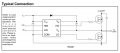
@ronsimpson Quick question. (Haven't had time to do more reading, but want to get something ordered before the weekend.) Would something like the Infineon IR2301 work to drive both MOSFETs? Highside is bootstrapped.

1784911983512.png
 

ronsimpson

Joined Oct 7, 2019
4,755
Yes. This drives a high-side MOSFET (N-mos) and a low side driver.
The top driver must be turned off part of the time. It cannot be on 100% of the time.
--edited--
The COM pin connects to the computer ground pin. The bottom MOSFET cannot go below ground. I think in one of you examples the bottom MOSFET sits below ground.
 
Top