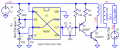
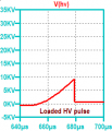
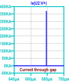
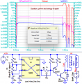
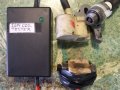
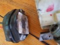
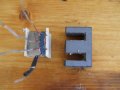
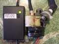
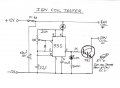
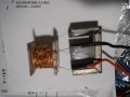
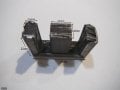
If you happen to come across later coils that are CDI or in built transistor type (no points) coils. Then this is what i made up to trigger them, using a modified E core transformer ground to shape. My coil tester is similar style using Ne555 & an Ign transistor.
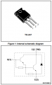
It is essential to have the primary zener diode, typically a 380-400V string to protect the ignition coil from insulation breakdown if the spark gap it too wide.
I have damaged (small) ignition coils while testing them, they arc'd and then shorted internally because the spark gap went too wide.
For these 555 ignition coil testers, I use automotive IGBT's which have the zener built in, example: FGP3040G2 IGBT comes in TO-220/D2PAK/DPAK/IPAK 400V 26A logic-level drive works great, fewer parts.
The SAE-standard ignition coil (secondary) load test is a 1,000V 5W zener string to clamp to the arc burn voltage of around 1,000V and it has a series resistor to GND so you can measure spark current with a scope.
It does not stress an ignition coil's insulation for the HV spark initiation, something you need to do a little to test a coil.
I followed this thread, which I had not seen before, and now I have a question or two:
FIRST, what aspect of the coil does the TS want to test? And second: Does the TS need more than a PASS/FAIL test?? Just exactly does the TS want to verify??
All that I have seen is circuits to drive the coil to make a string of sparks. That can be impressive, but that is not required for verification as to is it able to produce a spark.
ALL of those circuits are much more complex than is required, IFF the goal is simply to verify that the coil can produce sparks to run an engine.
For many years I have tested assorted ignition spark coils using only a battery and a "Known to be good" spark plug. The tricky portion of the scheme is avoiding giving ones self a nasty shock.
The requirements are being able to wire the parts AND having a spot shaded enough to allow actually seeing the spark. In addition to the being able to momentarily connect the battery to the coil's primary terminals momentarily. But the scheme does not deliver the constant sparking that the other circuits provide, it only delivers a spark when the battery connection is opened.
I followed this thread, which I had not seen before, and now I have a question or two:
FIRST, what aspect of the coil does the TS want to test? And second: Does the TS need more than a PASS/FAIL test?? Just exactly does the TS want to verify??
All that I have seen is circuits to drive the coil to make a string of sparks. That can be impressive, but that is not required for verification as to is it able to produce a spark.
ALL of those circuits are much more complex than is required, IFF the goal is simply to verify that the coil can produce sparks to run an engine.
1. I will try to explain your questions as simple as possible i can.
These old ignition coils can be "shorted" (bad) inside sometimes but also it gives a visible spark on the sparkplug but the engine wont run/start. (it does not make any sound when the spark jumps, if its bad it only jumps but no sound. I hope you can understand what i mean i tried my best to explain it from my experience.)
2. Pass/Fail and how far can spark jump.
Not all ignition coils are the same, some of them can give a spark but weak, while some can give really strong spark.
The point of the Ignition coil tester is to test the coils without opening the engine and mount them each one by one which can take a lot of time if you need to test bunch of them.
For many years I have tested assorted ignition spark coils using only a battery and a "Known to be good" spark plug. The tricky portion of the scheme is avoiding giving ones self a nasty shock.
The requirements are being able to wire the parts AND having a spot shaded enough to allow actually seeing the spark. In addition to the being able to momentarily connect the battery to the coil's primary terminals momentarily. But the scheme does not deliver the constant sparking that the other circuits provide, it only delivers a spark when the battery connection is opened.
I assume those are CDI ignitions and no point ignition?
these ignition coils that i want to test are working on 6V, but as the speed increase the voltage can go up so its not constant 6V.
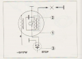
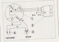
This schematic is for 6V point ignition.
This schematic is for 12V CDI ignition.
Observing the spark on a non-resistor spark plug with a larger gap, used for testing, and using either a six volt supply directly, or thru a ballast resistor, will reveal a lot about the spark coil performance and condition. What it DOES NOT show is if the spark becomes weaker as the dwell time decreases.
No, it isnot a "universal" tester, but it is adequate for a lot of ignition coils and about as cheap and easy as can be,
I advise picking up a waste-spark coil, scrap auto parts recycler , there are 4 of them on an 8 cyl motor!
I used an 8pin picmicro with a power mosfet but a 555 will also work.
When I wanted to test ignition coils I used an el cheap (inexpensive) every day incandescent bulb lamp dimmer. The cost is about $13 to $15 USD. I am in the US so it was a 120 VAC 600 Watt lamp dimmer. Simple, inexpensive and easily had about anywhere. Works fine and last a long time.
When I wanted to test ignition coils I used an el cheap (inexpensive) every day incandescent bulb lamp dimmer. The cost is about $13 to $15 USD. I am in the US so it was a 120 VAC 600 Watt lamp dimmer. Simple, inexpensive and easily had about anywhere. Works fine and last a long time.
I think that a lot of us need to understand how you did that! Please explain, BECAUSE I can see a lot of unsafe ways that could be attempted. And a couple of safe ways it could be done.
So please describe the safe way!!
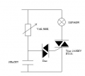
The coil is a re purposed Iron E core transformer re wound as a driver for small engine CDI or point less ignition systems. Included circuit, i used a IGN transistor from a car ECU as it was free from scrap yard.
What I DO NOT SEE is any explanation words about how the circuit and the coil assembly apply to any part of testing any sort of ignition system assembly. I can make a guess, but any of my guesses will require a fair number of assumptions, which may not be even close to correct.
What is missing are words describing how it works and what it does.
The coil is a re purposed Iron E core transformer re wound as a driver for small engine CDI or point less ignition systems. Included circuit, i used a IGN transistor from a car ECU as it was free from scrap yard.View attachment 367947View attachment 367948View attachment 367949
I think that a lot of us need to understand how you did that! Please explain, BECAUSE I can see a lot of unsafe ways that could be attempted. And a couple of safe ways it could be done.
So please describe the safe way!!
I will get with a moderator just to make I sure. However not much to it.
This is a basic lamp dimmer circuit:
Not much to it. The resistor and cap create a phase shift to gate the triac via the diac To fire the triac. To fire an ignition coil we want the flux density th collapse and collapse fast. Coil won't fire with a slow changing signal like a slow sine. The Triac in the dimmer gives the coil the needed fast collapse.
I know I have some motor cycles out in the garage and hopefully some plugs. Have a dimmer here somewhere so I will round up some parts. Not difficult but as you bring up safety concerns maybe I will run it past a moderator. Sorry but anyone who can't exercise caution can get bit in a bathtub. Anyway, give me a few days and I will toss something out. Using a dimmer is a little rough but not difficult. Likwly a dozen ways to test a coil.
OK, I see the very simple circuit, BUT I see nothing about how it might connect to anything. How is this circuit connected to test an ignition system spark coil?? THE test connection part is what is missing.
Really, there seems to be a lot of information missing. I had not realizad that shorted turns werea common failure mode. That is very much a new one to me. Open windings and shorts to ground are the failures I am aware of.
The ignition coil is connected the same way a lamp would be connected. Replacing lamp with coil. Now if I can just find the lamp dimmer which has to be here somewhere. I know I have one.

 Facebook
 Google
 GitHub
 Linkedin