Trying to add metering to a split rail bench power supply

Thread Starter

gray-b

Joined Aug 4, 2025
88
Advice is sought on adding metering to a split rail bench power supply. Is this correct as concerned about earthing/0v loops

I have a power supply with a single output (a paralleled split PSU), and split rails.

I have incorporated switching to enable this to be done. Or is this best if I just used jumpers on the output terminals. But how do I add voltmeters and ammeters?
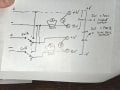
20260703_084345.jpg

Chinese dual digital V & I meters will have a separate auxiliary supply from a dcdc isolated supply. The Ammeter is measuring 20A across a shunt.

Single output - No problem, voltage straight across +output terminal and across 0v terminal. Current in the return path from 0v terminal. Believed the correct way to use the Chinese dual digital V & I meters and is not in the positive rail.

Dual (Split) Rail output - Again, voltage no problem as they are both across the output terminals +V 0V and 0V -V. The problem comes in trying to connect the ammeters. Assuming I use the same method as in the single output
 
Last edited by a moderator:

panic mode

Joined Oct 10, 2011
5,144
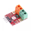
from what i have seen there are many cheap 3-digit modules but they are not very accurate. i would rather throw in pair of INA226 modules like this (note 0.002 Ohm shunt). these little guys are 16-bit measuring both voltage and current.
1783340247622.png
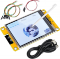
use CYD like this for CPU and display so one have not just values but also graphs and whatever else you like
1783340540286.png

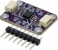
since two power rails are isolated, using I2C isolator such as ISO1540 would do.
1783340878396.png

the downside is that this is not ready to use out of box - it would also need to be programmed.
 
Last edited:

schmitt trigger

Joined Jul 12, 2010
2,163
Many moons ago I had a similar issue and used a level shifter and analog switches. But it required precision resistors and a high voltage opamp.
If I were to do again nowadays, I would follow instead Panic Mode’s excellent advice.
EDIT; it does require some software effort, but there are already application files for Arduino and other devices.
 

Irving

Joined Jan 30, 2016
5,195
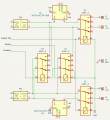
This is a simplified version of my digitally controlled PSU 2 x 30v @ 5A., with series/parallel option and output on/off. Note the interlock between K3 and K4 that prevents series and parallel being selected together. I use hall effect current monitors as they are isolated, bidirectional and so much less hassle. I have a separate ADS1115 16bit ADC for voltage and current on each channel. The voltage measurements, not shown, are on an isolated subsystem with an I2C isolator because the whole supply can be sat on an external voltage up to 600v (I had a need for one project....)

If I was doing it again, I'd think about putting the series/parallel relays on the outside of the output on/off relays. I was always in two minds about the series/parallel interlock - as it stands, selecting series overrides parallel, but it might be better the other way round - though in theory the software prevents it anyway.

[edit] also note, selecting parallel or serial turns output off before actioning, in sofware. Also turning output off, MCU shuts down PSUs first. Relays never switch high currents.

1783360857899.png
 
Last edited:

panic mode

Joined Oct 10, 2011
5,144
it does require some software effort, but there are already application files for Arduino and other devices.
exactly. btw INA226 and INA228 have exact same pinout. the software of course is different but one gets 20bit resolution and wider voltage range.
ACS7xx series products are also very nice but level shifting or better using isolated opamp would be needed.

as for writing code, i find that AI to be getting better and better at it. over the past few weeks i had couple of projects done in part or entirely by AI.
here i got marquee scroller with custom font and some effects all in about an hour - including setting up tool chain on a new computer from scratch, pasting code, compiling, debugging... while watching movie.
when there is a problem is just paste the message or compiler output and let the AI fix it. for things like this it would be perfect...
 

Irving

Joined Jan 30, 2016
5,195
ACS7xx series products are also very nice but level shifting or better using isolated opamp would be needed
No, they are hall-effect; the high-current path is magnetically isolated. So no level shifting etc needed. Vdd = 3.3v, Vdd/2 = 0A, 0.33v = -5A, 2.97v=+5A 264mV/A , noise about 1.7mv rms gives effective resolution of 6mA but can improve that with oversampling. ST, TI and others have similar products.
 

MisterBill2

Joined Jan 23, 2018
27,889
The problem with switching digital meters between different voltage sources is always the lack of isolation. Many of those digital meters do not have enough isolation between the measuement input circuit and the meter power supply circuit. For that class of meters the only solution is separate isolated power supplies for each meter.
Certainly that is inconvenient, but the alternative of isolation amplifiers for the inputs is quite complex.

Switching the meter inputs will always require adequate isolation of both the negative and positive sides, for which I am not aware of any simple electronic devices. Actual electromagnetic relay switches, or actual switches, are the only simple choice. The bad news is that it requires space and powerfor relays.
 

schmitt trigger

Joined Jul 12, 2010
2,163
Relays. In the past I have used reed relays for small signal purposes like this application. Compact, fast switching, low coil power and very low wetting current requirements.
However…… their cost has skyrocketed!
But I am sure that there are other conventional signal relays that could work.
 

MisterBill2

Joined Jan 23, 2018
27,889
An alternative to a lot of expensive relays is a two-pole rotary switch, which can connect both sides of the meter to either the correct series shunt resiator or that correct voltage divide tap, as required. THAT is the classic approach, which has been used very successfully for about a hundred years. BUT it is very important that such a switch be a "NON-SHORTING" variety!! (That means that the switch does not connect adjacent poles to each other while changing positions.) That can be checked quite simply!
 
Last edited:
Top