Trying to drive actuator from RC unit

Thread Starter

rjjenkins

Joined Apr 16, 2011
233
Hi
I am having a problem that leaves me baffled.
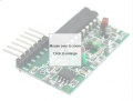
I have one of these cheap RC receiver modules
https://www.ebay.co.uk/itm/231418644091
Here is a picture
upload_2019-2-23_12-4-43.png

They are pretty simple - when a button is pressed on the transmit fob, the voltage on the corresponding receiver pin goes high. When the button is released the output goes low. They run on 5V.

I am trying to use it to power a rotary actuator that draws about 500mA peak. It is a shape memory alloy actuator so not quite like a motor. They are here http://www.migamotors.com/index.php?main_page=product_info&cPath=1&products_id=30

I am driving the actuator through a stp36nf06l mosfet, in the usual configuration - output of RC receiver module to gate, 100k resistor between gate and source, source to ground, and actuator between drain and VCC

Now here's the problem. When everything is connected, as soon as I press the button on the fob the output on the receiver goes high, and the actuator starts to move, but straight away the voltage on the output pin drops and the actuator stops. If I keep the button pressed, it tries again, so I get a kind of stuttering motion.

I am running all this at the moment from the bench PSU with plenty of power, and the voltage to the receiver module does not drop.

I can use the same configuration to operate the actuator from the output pins of an Arduino Uno with no problem so I don't think the problem lies with the actuator or mosfet circuit

I even tried replacing the mosfet with an optocoupler which draws negligible current but the same problem occurs. Basically as soon as any current is drawn from the power source, the receiver stops functioning, even though there is plenty of current available. (I mean, if the circuit can run from a UNO, why not from this unit?)

The only way I can fix it is to run the actuator from a separate power source but I don't want to have to do that.

Any ideas, please?
 

Attachments

mvas

Joined Jun 19, 2017
539
Does the voltage on the Output Pin of Receiver stay High / ON as long as the Button on Transmitter is pressed, when not connected to the MOSFET?
What is the voltage of the Output Pin when On ?
Is the Receiver Output Pin "Open Collector" or "Totem Pole" ?
Does the Receiver Output Pin require a Pull-Up Resistor?
We need spec's for the receiver output pin
 

ericgibbs

Joined Jan 29, 2010
21,439
hi rj,
My best estimate would be the as the actuator is energised the radiated electric noise is blotting out the RF section of the receive module.
Causing a 'sqegging' effect,
E
 

LesJones

Joined Jan 8, 2017
4,511
Can you post a schematic of EXACTLY how it is all connected together. The problem sounds like noise from the actuator interfering with the receiver. This is probably due to lack of decoupling and filtering.

Les.
 

Thread Starter

rjjenkins

Joined Apr 16, 2011
233
Does the voltage on the Output Pin of Receiver stay High / ON as long as the Button on Transmitter is pressed, when not connected to the MOSFET?

Yes

What is the voltage of the Output Pin when On ?

approx 5V

Is the Receiver Output Pin "Open Collector" or "Totem Pole" ?

I don't know

Does the Receiver Output Pin require a Pull-Up Resistor?

I don't think so but I wouldn't imagine it does. Its normal state is low, why would it need a pull up resistor? Sorry if I'm misunderstanding something

We need spec's for the receiver output pin

The only specs I have are in the ebay description
 

Thread Starter

rjjenkins

Joined Apr 16, 2011
233
hi rj,
My best estimate would be the as the actuator is energised the radiated electric noise is blotting out the RF section of the receive module.
Causing a 'sqegging' effect,
E
It's possible and I hadn't thought of that, but I am running the actuator some distance from the receiver at the moment (about 30cm). I will try further.
 

Thread Starter

rjjenkins

Joined Apr 16, 2011
233
Can you post a schematic of EXACTLY how it is all connected together. The problem sounds like noise from the actuator interfering with the receiver. This is probably due to lack of decoupling and filtering.

Les.
See below. No decoupling or filtering . I've put in a motor symbol but it is not a motor. The actuator works with shape memory metal wire - when it heats up (because a current passes through it), it contracts in length. It is really not much more than a fancy low value resistor so I would not expect it to be producing much RF interference if any.


upload_2019-2-23_13-43-5.png
 

djsfantasi

Joined Apr 11, 2010
9,237
These type of actuators require a LARGE amount of current to operate. Is your 500mA figure a measured value? The page you linked to doesn’t have electrical characteristics. Some of these actuators draw in the order of 4A

Unlike the Uno, there is no onboard voltage regulation. I suspect the current draw is causing a voltage sag to the receiver. The Uno works because of the onboard regulation.

I’d suggest separate power sources but won’t because you don’t want to do that.
 
Last edited:

Thread Starter

rjjenkins

Joined Apr 16, 2011
233
Yes the 500mA is my measured value. I can't find a datasheet for the actuator. The actuator is meant to oscillate back and forth so the current is not steady and it's hard to be sure what the peak is. However, I can't detect any drop in the input voltage, and the bench PSU is capable of delivering 5A.

But if it is causing a momentary voltage sag, is there any way to compensate for that?
 

KeithWalker

Joined Jul 10, 2017
3,607
Yes the 500mA is my measured value. I can't find a datasheet for the actuator. The actuator is meant to oscillate back and forth so the current is not steady and it's hard to be sure what the peak is. However, I can't detect any drop in the input voltage, and the bench PSU is capable of delivering 5A.

But if it is causing a momentary voltage sag, is there any way to compensate for that?
Try decoupling the supply to the receiver using an inductor and capacitor. This will block transient switching spikes that could interfere with the receiver.
 

jpanhalt

Joined Jan 18, 2008
11,087
Your link shows a 7-pin connector with the VT pin at the opposite end from power. You seem to be using a data pin. Do you know what the data out looks like? Why not use the VT pin?

upload_2019-2-23_10-2-49.png
 

Thread Starter

rjjenkins

Joined Apr 16, 2011
233
Now the receiver has stopped working altogether ... will have to wait for a new one to come from China. Thanks for all advice.
 

Thread Starter

rjjenkins

Joined Apr 16, 2011
233
Your link shows a 7-pin connector with the VT pin at the opposite end from power. You seem to be using a data pin. Do you know what the data out looks like? Why not use the VT pin?

View attachment 170816
Yes - have to admit I don't understand this. The first two pins are GND and +5V. The next pins correspond to the four channels on the transmit fob and go high when the relevant button is pushed. I don't actually understand what the VT pin does.
 

shortbus

Joined Sep 30, 2009
10,050
I went up to 7V and it didn't make much difference. I didn't want to go higher because I didn't know the true absolute rating of the unit
The data sheet says 18Volts, and that is called "Vgs" or votltage gate to source. Your operating close to the threshold of the mosfet, the point where it is just conducting, and has the highest resistance when turned on. It looks like the mosfet will operate there but it likes to be at ~10V much more. When both the on resistance of the mosfet and the actuator are added together it may be dragging the circuit down and causing some of your problems. Maybe look at some real "logic level" mosfets instead of one that 'kind of' works at that low of a gate voltage. Logic level mosfets are fully turned on at around 5V, there are many out there to chose from.
 

LesJones

Joined Jan 8, 2017
4,511
I don't think the problem is related to the gate drive voltage to the MOSFET. Here is a link to the data sheet for the STP36NF06L. It shows the on resistance of 0.05 ohms (Max.) with a gate drive of 5 volts and a source to drain current of 15 amps.
I suggest doing the following modifications. Connect a ceramic capacitor about 10 nF directly across the connections to the actuator. (Or if you can get to the motor directly across the brush connections.) If you have ant ferrite beads thread some on the wires to the actuator close to the actuator. (These things are to try to reduce radiated interference from the wires to the actuator.) Connect the negative power lead close to the MOSFET source. Connect the positive power lead close to the actuator. Connect a diode in series with the positive supply to the receiver. (A Schottky diode if possible to reduce the voltage drop.) Connect a fairly large value capacitor (Say 1000 uF) across the power leads to the receiver on the receiver side of the diode. This it reduce the effect of dips in the power supply voltage to the receiver. A ceramic capacitor (10 to 100 nF) close to the receiver may help to reduce interference getting into the receiver via the power leads.

Les.
 

Thread Starter

rjjenkins

Joined Apr 16, 2011
233
I agree I don't think it's the mosfet, which in fact will turn on the actuator with a VGS of around 3.5V
I will try your suggestions (though of course there are no brushes because this is not a motor)
 

LesJones

Joined Jan 8, 2017
4,511
I wrongly assumed it was an actuator that uses a threaded rod driven by a motor. (I have only just looked at the link to your actuator.) I will have to try to find out how they work to understand if they are likely to generate interference of any kind.

Les.
 

djsfantasi

Joined Apr 11, 2010
9,237
Yes the 500mA is my measured value. I can't find a datasheet for the actuator. The actuator is meant to oscillate back and forth so the current is not steady and it's hard to be sure what the peak is. However, I can't detect any drop in the input voltage, and the bench PSU is capable of delivering 5A.

But if it is causing a momentary voltage sag, is there any way to compensate for that?
Ok, 0.5A is your measured value. Did you measure it while the actuator is being activated?

Also, shortbus’ post contains valuable information.

I’ve used these receivers. You said you didn’t understand what VT was. VT goes high when any of the channels are activated.

As far as the MOSFET specifications, regardless of what you think, 5VDC is not sufficient to switch the actuator on. You definitely need a “logic level n channel MOSFET” rated at 1A. Use the quoted description for a parts search. Otherwise it won’t have reliable operation.

And another point. The receiver specifications DO say 5V power source. I’d double check. The receivers I’ve used actually require 12V. Their output is 5V, but the actual receiver needed 12V.

And my last observation. I note that the specifications include the requirement of an external antenna. Other receivers I have purchased include the antenna on board. You haven’t mentioned it yet, so I wonder what antenna you have for the receiver?
 
Top