 Facebook
 Google
 GitHub
 Linkedin
Hi All,
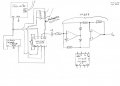
Here is a link to the circuit diagram and other images that may be useful
I've been looking at creating a circuit that take the signal from a muscle amplifies it using an In-Amp and then rectify it using a precision rectifier. I've been using the circuit diagram in this pdf I got from a chap on reddit as a reference I have the precision rectifier working and I can put + or - 5V in to it and it ouputs +5V both times but I don't seem to be able to get an amplified voltage out of the In-Amp. No matter what it seems to just supply 5V permanently no matter the gain or input. Originally I thought the in amp was busted so I bought a few others to try (CJMCU-29, CJMCU-8221, INA-126P) but they all have the same problem so it must be something I'm doing wrong. The output I'm looking for is a varying voltage depending on how much the muscle if contracted in this case my bicep. The electrodes I am using on my arm are some stainless steel bolt heads on the inside of some bands I 3D printed that way I can use crocodile clips on threaded part of the bolt to connect the electrodes to the circuit. I might be a little bit in over my head with this project but that's where I tend to learn the most. Sorry if I haven't provided any information that is needed but I will do my best to add anything that is needed. Thanks in advance.
Attachments
-
 122.6 KB Views: 27
 -
 137.5 KB Views: 28
 -
 95.8 KB Views: 32

")


