Facebook
 Google
 GitHub
 Linkedin
A couple of comments on what @TeeKay6 just posted:@Rossosaurus
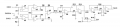
As @Vinnie90 has recommended, consider DC-blocking caps at the + and - inputs, but not at the Ref input. In Vinnie90's schematic, also note R1 and R2. The input bias currents of the INA126 still need a path to ground. Thus R1 and R2 provide that path and unfortunately, at the same time, provide additional load on the myoelectric source and, also unfortunately at the same time, create interfering voltages (Ibias*R). Thus there will be some best compromise values for C1,C2,R1,R2. An INA with low input bias currents is therefore an advantage. The INA126 is not among the low input bias current INA's but it is among the low cost INA's. I have not kept current on what the market offers for INA's so I don't have a recommendation.
Perhaps other commenters (including typo-prone @Vinnie90) can offer INA suggestions?
- In addition to the noise consideration you should also consider where you place the pole for the RC section (in principle you want it as low as possible to cut only the DC component and not useful frequency content, however this usually requires a pretty big value for R from which the Ibias consideration)
- I think a good way to avoid that is to use a dual op amp so that the Ibias are kind of matched and therefore they can be rejected by the Differential amplifier (which remember has a very high CMRR)
But yes in general better to use JFET buffer input because I think that the vast majority of cheap Instrumentation amplifiers have bipolar inputs (not sure on that tho)