 Facebook
 Google
 GitHub
 Linkedin
@TeeKay6 @Vinnie90
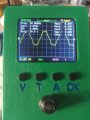
Afternoon chaps, bet you didn't think you'd hear from me again. Today I finally managed to get some time to work on this project. I started by putting a band pass filter on each of the 2 muscle signal inputs but not the reference. I checked that they worked first with a function generator and they did so I connected them up to the INA. I also set the gain to ~160 as by my calculations the amplifier was only increasing the signal to about 1.6V at its peak. Anyway, I have a circuit together now with band pass filters on each muscle input to keep the signal to ~5-500Hz but I'm still not getting a signal that increases and decreases with muscle contractions. I've attached an image of the circuit diagram, the output on my oscilloscope and the layout on the breadboard (Not that the last one will probably help much). The 10uF caps are electrolytic for no reason other than they were within arms reach at the time. The 0.1uF caps are ceramic.
Tah
Attachments
-
 4.2 MB Views: 7
 -
 1.7 MB Views: 4
 -
 6 MB Views: 3


