Troubleshooting an old color organ circuit

Thread Starter

chuco61

Joined Jan 21, 2015
80
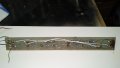
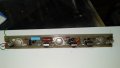
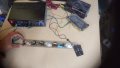
I have a 12v color organ that does not react or operate as it should. I have been testing all of the components to see if they are in working order with a multi-meter. The switch has also been replaced with a working one (temporarily)

I believe that the transistors are bad as all of the contacts are reading on the multimeter. Is it safe to assume they need replacement?

This appears to be a three-channel circuit, so how would I go about purchasing transistors to keep the channels separate?
 

Attachments

MrChips

Joined Oct 2, 2009
30,706
There are limited tests you can perform with a DMM.
Firstly, we need to reverse engineer the board.
Somebody has to be able to trace the connections and make a circuit drawing.
Show us close-up photos of the board around each transistor, both sides of the board (total of 6 photos).
 

Ian0

Joined Aug 7, 2020
9,667
Those transistors are in TO3 cases, and TO3 cased transistors are still available, maybe not the originals, but certainly a replacement. is there a part number on the transistor case?
How did you test them with a multimeter.? You probably won’t get a meaningful result unless you remove them from the circuit.
 

Thread Starter

chuco61

Joined Jan 21, 2015
80
What did these tests involve? Do you have access to an oscilloscope? Even a cheap one would be more useful then your DMM.
I tested all terminals with the negative, then the positive probes of the DMM. All returned readings where I think they shouldn't but I could be wrong (from what I read, this will help determine if it's an NPN or PPN). I don't have an oscilloscope.
 

Thread Starter

chuco61

Joined Jan 21, 2015
80
Those transistors are in TO3 cases, and TO3 cased transistors are still available, maybe not the originals, but certainly a replacement. is there a part number on the transistor case?
How did you test them with a multimeter.? You probably won’t get a meaningful result unless you remove them from the circuit.
There are no identifying markings on the transistors - maybe underneath on the board side? Thanks for clarifying the type! Do they sell these in different variances to help with the channel separation or is that done through the rest of the circuit?

I tested them using both + and - probes of the multimeter while on the board. I can remove them and don't mind replacing them.
 

dl324

Joined Mar 30, 2015
16,839
I tested all terminals with the negative, then the positive probes of the DMM. All returned readings where I think they shouldn't but I could be wrong (from what I read, this will help determine if it's an NPN or PPN).
What were the DMM leads connected to? What setting was it on? You can't do more junction tests on a transistor that's in circuit. Even then, whether the results are definitive depend on what components are in parallel with the junctions.
I don't have an oscilloscope.
You can have a cheap digital scope for $20-40 dollars. A scope is a more appropriate tool for troubleshooting a color organ.
 

Ian0

Joined Aug 7, 2020
9,667
Does you meter have a "diode test" function. If so you can check the transistors, but first you will have to remove them from the circuit. They may be old enough to be germanium, so you need to be careful and not let them get too hot.
All three transistors will be the same, and they seem to be well on top of the job for the size of lamps they are switching, my guess is that they will have survived.
I see some inductors and capacitors around each transistor, so I think this is a sound-to-light unit with channels for bass, mid and treble.
What does it do at the moment?
 

bertus

Joined Apr 5, 2008
22,270
Hello,

You might see that the pins of the transistor are not in the middle of it.
That way you can determine the Base and Emittor, the case is most times the Collector:
TO3 pins.png
The transistor will likely have a style 1 connection.

Bertus
 

Thread Starter

chuco61

Joined Jan 21, 2015
80
Does you meter have a "diode test" function. If so you can check the transistors, but first you will have to remove them from the circuit. They may be old enough to be germanium, so you need to be careful and not let them get too hot.
All three transistors will be the same, and they seem to be well on top of the job for the size of lamps they are switching, my guess is that they will have survived.
I see some inductors and capacitors around each transistor, so I think this is a sound-to-light unit with channels for bass, mid and treble.
What does it do at the moment?
Yes this is a sound to light bar that is intended for a car. I think it's from the late 70's. At the moment, only three of the bulb filaments will slightly glow and that's about it.

I do have a diode test function on my DMM.
 

Thread Starter

chuco61

Joined Jan 21, 2015
80
What were the DMM leads connected to? What setting was it on? You can't do more junction tests on a transistor that's in circuit. Even then, whether the results are definitive depend on what components are in parallel with the junctions.
You can have a cheap digital scope for $20-40 dollars. A scope is a more appropriate tool for troubleshooting a color organ.
I cant remember, but I think I had it at 200K ohm. I'll work on removing them from the board.
 

dl324

Joined Mar 30, 2015
16,839
I cant remember, but I think I had it at 200K ohm.
Resistance checks won't give any useful information on transistors. You can often check junctions, but that won't tell you if the transistor has high leakage.
I'll work on removing them from the board.
Why remove components unless you have reason to suspect that they're bad? You can measure voltages to see if they're biasing correctly, but a scope would allow you to trace the signal at the outputs of each filter and the corresponding transistor outputs.

The board doesn't have many components and is single sided. It should be straightforward you to trace circuit and make a schematic. With that, we'll have a better idea of what to have you check.
 

Thread Starter

chuco61

Joined Jan 21, 2015
80
Resistance checks won't give any useful information on transistors. You can often check junctions, but that won't tell you if the transistor has high leakage.
Why remove components unless you have reason to suspect that they're bad? You can measure voltages to see if they're biasing correctly, but a scope would allow you to trace the signal at the outputs of each filter and the corresponding transistor outputs.

The board doesn't have many components and is single sided. It should be straightforward you to trace circuit and make a schematic. With that, we'll have a better idea of what to have you check.
Unfortunately, I think that is beyond my skill set. I can solder and desolder and replace. I'm just not skilled enough to trace this out I feel.

I mean, shoot, I could replace each component with a new one, but might just be spinning my wheels.
 

dl324

Joined Mar 30, 2015
16,839
Unfortunately, I think that is beyond my skill set.
Tracing such a simple circuit and making a schematic is easy. Post clearly focused pictures of the top and bottom of the left part of the board and I can demonstrate.

The circuit will likely turn out to be something like this:
1636588242264.png
A signal going though some passive filters. Except you have incandescent lamps instead of LEDs.
 

Ian0

Joined Aug 7, 2020
9,667
Yes this is a sound to light bar that is intended for a car. I think it's from the late 70's. At the moment, only three of the bulb filaments will slightly glow and that's about it.

I do have a diode test function on my DMM.
Do a diode test on the two pins, and note whether you get a reading with the red lead to the base, or with the red lead to the emitter.
Do another diode test between the base pin (from @bertus ‘s diagram) and the case. You should get reading one way round but not the other.
The repeat between emitter and case. You should get no reading either way round.
if the base-emitter reading is above 0.5 then it is probably a silicon Transistor, below 0.2 germanium.
 

dl324

Joined Mar 30, 2015
16,839
The component circled in red might also be a transistor:
1636644434825.png

You can check the power transistor junctions by putting your DMM in diode check. Then put the positive lead on the base and probe the emitter and collector terminals. If you get open readings, reverse the leads and test again.

If the component circled is a transistor, the leads will be in a triangular arrangement and the base will probably be the middle lead. If so, you can check those transistors the same way you checked the power transistors. The flat edge is used for orientation.
 

Thread Starter

chuco61

Joined Jan 21, 2015
80
The component circled in red might also be a transistor:
View attachment 252418

You can check the power transistor junctions by putting your DMM in diode check. Then put the positive lead on the base and probe the emitter and collector terminals. If you get open readings, reverse the leads and test again.

If the component circled is a transistor, the leads will be in a triangular arrangement and the base will probably be the middle lead. If so, you can check those transistors the same way you checked the power transistors. The flat edge is used for orientation.
I was confused about this part as well. I think it is a transistor as it does have three leads. If it is indeed a transistor, what era is this from? 1970s? Will check later tonight.
 

Thread Starter

chuco61

Joined Jan 21, 2015
80
Tracing such a simple circuit and making a schematic is easy. Post clearly focused pictures of the top and bottom of the left part of the board and I can demonstrate.

The circuit will likely turn out to be something like this:
View attachment 252350
A signal going though some passive filters. Except you have incandescent lamps instead of LEDs.
I really envy your skills at being able to do this. It's just beyond my comprehension, I suppose I just dont have enough experience reading these. Testing and replacing is about as far as I can get at this point haha.
 

Attachments

Top