Troubleshooting an old color organ circuit

MrChips

Joined Oct 2, 2009
35,018
I was using those of examples of how to tell which end to read from. The only resistor value in question is R4A. Color code given was violet-red-yellow and that doesn't give a valid 10% (E12) value.

We still don't have transistor polarity. I'm waiting on that, the transformer pinouts, and clearer pictures of the bottom before investing more time.
E12 values for the first two colours are:
10 brown black
12 brown red
15 brown green
18 brown gray
22 red red
27 red violet
33 orange orange
39 orange white
47 yellow violet
56 green blue
68 blue gray
82 gray red

The third colour is the multiplier, e.g. yellow = x 10k
The fourth colour is the tolerance, e.g. silver = 10%

1637180920889.png
 

Thread Starter

chuco61

Joined Jan 21, 2015
80
I still don't see that. Could you take a higher resolution, clearly focused picture of that area?I rotated and mirrored the picture to make associating traces with components easier.
View attachment 252904
If they were connected, it could have been done in a better place. It looks like it just ends to me.

In your defense, the resistors were marked poorly.
View attachment 252906
The "gap" between orange and silver on R4 is barely discernable. On R3, there is no discernable gap; you just have to know that silver is never a valid first band.

EDIT: Just looked at some resistors I had on my bench and the "gap" isn't a sure thing. If you use resistors long enough, you become familiar with the standard values and use that familiarity to recognize the correct value.
Judging by the way the resistors are marked, how old would you sat this board is?

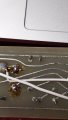
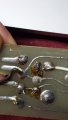
Also here are two images of the traces in question. Sorry the orientation is flipped for the ground lead.
 

Attachments

Thread Starter

chuco61

Joined Jan 21, 2015
80
I was using those of examples of how to tell which end to read from. The only resistor value in question is R4A. Color code given was violet-red-yellow and that doesn't give a valid 10% (E12) value.

We still don't have transistor polarity. I'm waiting on that, the transformer pinouts, and clearer pictures of the bottom before investing more time.
Getting close, I'll try to figure these out in the morning. Thank you all for your time helping me with this.
 

Thread Starter

chuco61

Joined Jan 21, 2015
80
I didn't mean for you to post the correct order for the codes that were backwards. I meant to inform you that there is a correct order (but resistors aren't polarized). The tolerance, temperature coefficient, and fail rate bands, if they're present, are typically spaced away from the bands for resistor value.
That still doesn't identify the polarity (NPN or PNP). There are what appears to be 3 other transistors that are in a black or brown package with their leads in a straight line.

You can determine transistor polarity with your DMM in diode check mode. If they're NPN, you'll read diodes with the positive lead on the base and the negative lead on emitter or collector. PNP would be the opposite; negative on the base and positive on emitter or collector.
Use your DMM to find which pins have a low resistance.
The silver transistors are PNP. I am having a hard time detecting polarity on the smaller round transistors. I am not sure if this is because the soldering is old or not and trying to determine what pin is the center is difficult as the leads are equally spread around the transistor base. There is a small imprint on the edge that reads WEC 3 and these have a rounded globe top.
 

dl324

Joined Mar 30, 2015
18,448
I am having a hard time detecting polarity on the smaller round transistors. I am not sure if this is because the soldering is old or not and trying to determine what pin is the center is difficult as the leads are equally spread around the transistor base.
There are only 3 commonly used pinouts: EBC, CBE, and BCE. Check pairs of pins until you get a diode reading and then try to find the other junction which will be between the other lead and one of the ones where you found a junction.
 

dl324

Joined Mar 30, 2015
18,448
The transistors are style 1 from the previous post by Bertus.
This doesn't make sense because that would have the bases of the 3 power transistors connected.
Take that back. My rotated/mirrored image confused me.
 
Last edited:

Thread Starter

chuco61

Joined Jan 21, 2015
80
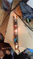
An interesting update. I found a wall wart with a higher amp rating (12v 3A) and hooked it up to the board. + to the red lead on the board and - to (mistakenly) the two green leads on the board (total brain fart) to my surprise the board lit up! See the photo, they were slightly reacting to the "noise" of the wall wart. as you can see most lit up, the other did light but much more faint.

When I hook up the + to red and - to black and green to a speaker output, nothing happens, so this makes me wonder how to even wire this thing. Typically there would be a positive, negative, and signal from the speakers.
 

Attachments

Thread Starter

chuco61

Joined Jan 21, 2015
80
Still working on this color organ. I have it all wired and working, but the first bulb labeled M will not react like its counterpart on the board. Any tips where I can start? I've tried jumping the bulbs together, but that didnt produce any meaningful results.


bassbindevil

Joined Jan 23, 2014
924
About the transistors... I got some little surplus amplifier boards from Poly Paks back in the '70s that had transistors like that, so I'd date them from the late '60s to early '70s.
 

Thread Starter

chuco61

Joined Jan 21, 2015
80
I am also trying upgrade the bulbs to some that are more easily found, these bi-pin bulbs are hard to come by. I found some E10 bulbs and bases that fit, however, I cannot get the replacement bulb to light bright, it seems as if they are too resistant ..? I've tried 2v bulbs and 12v bulbs without luck. Could it be the amp rating?

The voltage at the current installed bulbs max out around 5v.
 

Thread Starter

chuco61

Joined Jan 21, 2015
80
About the transistors... I got some little surplus amplifier boards from Poly Paks back in the '70s that had transistors like that, so I'd date them from the late '60s to early '70s.
I was told by someone else that this could possibly be a homemade unit based off of a kit, but the time frame is exactly what you say. Thanks!
 

dl324

Joined Mar 30, 2015
18,448
Any tips where I can start?
Can you trace the components around the bulb that isn't working correctly so we can see what frequency it's supposed to respond to? Have you tried swapping bulbs to see if it's the bulb? Do you have access to an oscilloscope?
 

Thread Starter

chuco61

Joined Jan 21, 2015
80
Can you trace the components around the bulb that isn't working correctly so we can see what frequency it's supposed to respond to? Have you tried swapping bulbs to see if it's the bulb? Do you have access to an oscilloscope?
I played a Hz test on youtube while this was hooked up and it responds to the "mid" tones of the sounds, It definitely wants to react like the other "mid" tone bulb - it just barely lights. I have not tried to replace the bulb as I cannot find any that match, that's why I'm trying to upgrade it. I don't have an oscilloscope.
 

bassbindevil

Joined Jan 23, 2014
924
I was told by someone else that this could possibly be a homemade unit based off of a kit, but the time frame is exactly what you say. Thanks!
It looks like it was wave-soldered, so probably not a kit. They might have sourced old components on the surplus market to cut costs, or used stuff that was already in inventory, if this was made by a big car audio brand.
If you can find old JC Whitney catalogs online (or the swap meet, if those ever happen again), they could have sold something like this.
I would trace the schematic, and pull some of the transistors to test them in a $20 Aliexpress component tester, which should give some clues as to what they are. Once you have a schematic, we can suggest more stuff to check.
 
Top