Shortcircuit diode troubleshooting

Thread Starter

andrew74

Joined Jul 25, 2022
270
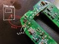
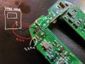
Hi everyone, I'm trying to figure out what's wrong with this mini remote control used to open a gate.

In the middle space you see in the photo, there was a small battery that's charged (now I removed it), and when you press the buttons, the two LEDs (on the button) light up, but the gate doesn't open.

I checked that all the resistors had the right value and that there were no short circuits in the capacitors.

So I was analyzing what I think is a diode for which I attach the datasheet.
https://www.mouser.com/datasheet/2/...oOSiRTamsQaSlfa_Zckhu1zt36v1iDDzv5e673qDRh1c_

Mostly, in the two nearby capacitors, I measure a resistive value that isn't infinite, like in all the others in the circui

The first question is whether I'm correct in saying that the diode burned out at one of the two anodes, and the second question is whether the resistance seen across those two capacitors could be provided by a parallel resistor

1000302455.jpg
 

Attachments

WBahn

Joined Mar 31, 2012
33,155
In general, you can't measure component values while the component is in a circuit. When you try to measure the across the capacitor, for instance, all you are doing is measuring the effective DC resistance of everything else connected to that capacitor. It's a meaningless measurement.

It's hard to really say if the measurement across the diode (if that's what it is) indicates a short circuited diode or not. Again, you have everything else in the circuit confounding the meter's ability to make a meaningful measurement. You need to lift at least the cathode off the PCB.
 

panic mode

Joined Oct 10, 2011
5,231
when i work on something, i try to first get the power rails identified, as well as major components and connections to surrounding parts. component you are looking at may be BAV70 and probably many other things - there is a lot of products in that form factor and just as many with marking A4:
https://smd.yooneed.one/code4134.html#code4134

i would suggest to first see the scale of part (is it really SOT-23 package), try to power it up and measure voltages around it. btw when testing not powered circuit with continuity tester, always swap probes to get readings from each direction. what you see is DC resistance but since many parts are polarized (diodes, transistors,...) getting bigger picture is important.
 

Pyrex

Joined Feb 16, 2022
546
First of all, how did you determine that the remote control isn’t working, and not the signal receiver at the gate that receives the signal?
Secondly, as I understand, the remote control sends a radio signal? If so, first you need to make sure that the remote control is sending a radio signal.
And your earlier measurements are of little use, as was mentioned in previous posts
 

Thread Starter

andrew74

Joined Jul 25, 2022
270
First of all, how did you determine that the remote control isn’t working, and not the signal receiver at the gate that receives the signal?
Secondly, as I understand, the remote control sends a radio signal? If so, first you need to make sure that the remote control is sending a radio signal.
And your earlier measurements are of little use, as was mentioned in previous posts
Hi! How do I verify if it is actually sending a signal?
 

Thread Starter

andrew74

Joined Jul 25, 2022
270
In general, you can't measure component values while the component is in a circuit. When you try to measure the across the capacitor, for instance, all you are doing is measuring the effective DC resistance of everything else connected to that capacitor. It's a meaningless measurement.

It's hard to really say if the measurement across the diode (if that's what it is) indicates a short circuited diode or not. Again, you have everything else in the circuit confounding the meter's ability to make a meaningful measurement. You need to lift at least the cathode off the PCB.
In general, you can't measure component values while the component is in a circuit. When you try to measure the across the capacitor, for instance, all you are doing is measuring the effective DC resistance of everything else connected to that capacitor. It's a meaningless measurement.

It's hard to really say if the measurement across the diode (if that's what it is) indicates a short circuited diode or not. Again, you have everything else in the circuit confounding the meter's ability to make a meaningful measurement. You need to lift at least the cathode off the PCB.
Thanks for the advice, I'll try it.
I'm also asking if you have any suggestions on how to check if the radio signal is coming out of the pcb
 
Hi! How do I verify if it is actually sending a signal?
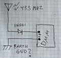
Likely a 315 or 433 MHz telemetry signal of which you should see something on a scope of sufficient BW and certainly with a spectrum analyzer. With a scope you can do a direct connection but with an analyzer a noncontact RF loop would be recommended.
 

MrChips

Joined Oct 2, 2009
35,146
Certainly, a spectrum analyzer would be useful for detecting an RF signal.
You can turn your PC into an RF spectrum analyzer by using SDR USB module (SDR = software defined radio).
 

MisterBill2

Joined Jan 23, 2018
28,215
Now I realize that we have all been assuming that it is a remote control failure. Has it been verified that the gate system is OK?? A poppedfuse or tripped breaker would also prevent a gate from opening.
In addition, really, has it been verified that the rest of the gate system is functioning correctly?? I HAVE been requested to repair systems that I found had simply suffered a mains power disconnection.
In the service business it is usually wise to check for the obvious first.
 
Top