Facebook
 Google
 GitHub
 Linkedin

Hello everyone, I’d like to ask your opinion on the design of an input stage.
I’m designing the input stage of a 48V three-phase inverter for PMSM motor control and I’d like your opinion on my reasoning. I’ve chosen this diode and this fuse.
The input and output parameters are shown in the photo (the ranges for Vi, Ii and the corresponding inrush current at the input), and two solutions are also shown:
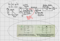
What I’m asking you to do is to check the diode and fuse chosen and, if they are wrong, help me choose a TVS diode and fuse that will ensure the circuit operates correctly under normal conditions and shuts down properly in the event of either of the following two conditions:
However, I’m afraid I may have made a mistake, as the Vclamp=93V of the TVS diode I’ve chosen is considerably higher than the Vin,max=66V of the DC-DC converter I’m using.
So can you confirm that I should look for a diode with Vrwm > 50V but Vclamp < 66V (assuming such a diode exists)?
.. although I believe that, unfortunately, almost no standard TVS meets this requirement
Does it make sense to connect a Zener diode with a breakdown voltage of 60V in parallel with the TVS?
I’ve also read online about more advanced crowbar circuits that include a MOSFET, but I want to understand all the pros/cons and limitations of this simple diode-and-fuse solution first, so please let’s not stray into circuits other than the simple one shown in the photo in this post. So, if you think it is possible to meet the two conditions highlighted earlier simply by choosing a diode and a fuse, then I would like to work with you to size them correctly
LET’S ASSUME we can’t reduce the inrush current… so please let’s focus on the situation described above; I want to learn how to select the correct fuse and diode in the event of an inrush current.
I’m designing the input stage of a 48V three-phase inverter for PMSM motor control and I’d like your opinion on my reasoning. I’ve chosen this diode and this fuse.
The input and output parameters are shown in the photo (the ranges for Vi, Ii and the corresponding inrush current at the input), and two solutions are also shown:
- the first is ‘simpler’ as it only uses a diode and a fuse;
- the second (I haven’t worked it out in detail; I’ve just included it amongst the options) is more sophisticated.
What I’m asking you to do is to check the diode and fuse chosen and, if they are wrong, help me choose a TVS diode and fuse that will ensure the circuit operates correctly under normal conditions and shuts down properly in the event of either of the following two conditions:
- reversed input polarity (the diode must conduct in the forward direction and the fuse must blow)
- overvoltage exceeding the Vi,max of the DC-DC converter used (the fuse does not blow and the diode conducts in reverse, limiting Vi to its Vclamp)
However, I’m afraid I may have made a mistake, as the Vclamp=93V of the TVS diode I’ve chosen is considerably higher than the Vin,max=66V of the DC-DC converter I’m using.
So can you confirm that I should look for a diode with Vrwm > 50V but Vclamp < 66V (assuming such a diode exists)?
.. although I believe that, unfortunately, almost no standard TVS meets this requirement
Does it make sense to connect a Zener diode with a breakdown voltage of 60V in parallel with the TVS?
I’ve also read online about more advanced crowbar circuits that include a MOSFET, but I want to understand all the pros/cons and limitations of this simple diode-and-fuse solution first, so please let’s not stray into circuits other than the simple one shown in the photo in this post. So, if you think it is possible to meet the two conditions highlighted earlier simply by choosing a diode and a fuse, then I would like to work with you to size them correctly
LET’S ASSUME we can’t reduce the inrush current… so please let’s focus on the situation described above; I want to learn how to select the correct fuse and diode in the event of an inrush current.
Last edited: