troubleshooting a tv power supply

Thread Starter

johndoe45

Joined Jan 30, 2010
364
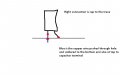
here is a vacuum pen. don't know if the price is too high, but wasn't looking to buy one anytime soon as i don't have a rework station. just a 750 degrees fahrenheit heat gun that will probably stop working soon. was really cheap at home depot.
http://www.electronix.com/penvac-pro-esd-safe-pen-vacuum-tool-p-13028.html
lifts a maximum of 500 grams = 1.10231131 pounds

on my way to go get desoldering iron from radioshack
 
Last edited:

Thread Starter

johndoe45

Joined Jan 30, 2010
364
here are all my mess ups. Oh My God! That radioshack desoldering gun does the trick. I got these 4 capacitors out so fast to show yall the messed up tracks.

well the red circles are the messed up tracks.

and the white circles are where I just soldered the capacitor to the scraped off peice of the track.

How can I fix the other parts???? Just scrape around the through hole and solder or am i going to have to do this like i did the fuse :confused:
 

Attachments

Jotto

Joined Apr 1, 2011
151
Not a biggie, take your time and run the leads of the caps to any trace that is right next to it. Now on the ones that the trace is on the other side of the board, approach it like this. If you have liquid flux dab a little on the component and let it flow down into the other side,or paste before putting the component in place put some flux at the bottom of the cap on each lead, this will help the solder flow down.

Your not the first to do this or the last.

The solder used in lap flow soldering is not like what we use to solder with. First when desoldering add some solder to the component before trying to suck the solder out. Or add some solder and slowly pull the component out one side at a time, but don't try to take it out completely on the first time, it will need 2 or 3 times before it falls out. Apply pressure, but not a lot of pressure.

An look for the pads if you have them use them, they are usually in your solder.

Also go to the welding shop, they have a drill set for cleaning tips, which work great for us to drill very small holes. Its a pen vise type tool, it holds the bits inside. They should be around 20 also, maybe less. I have had mine for 20 years so I haven't bought anything but drill bits for it.

If your planning on doing a lot of work one day, research trace repair kits, you can put in thru hole eyelets, traces and such. I will say this, I don't use them often because you can usually repair the unit without having to do that. They do make it look much nicer, but if it works ... it works.
 
Last edited:

Thread Starter

johndoe45

Joined Jan 30, 2010
364
so from the first picture,

the red circles are fine and the white circles i need to find track on top?

on other three pictures,

are the red lines where i would cut on the top?

and on the last picture i can't tell where to cut with the blue lines? or can choose either. of course not cutting as far back but didn't want to cover near the hole so you could see for yourself
 

Attachments

Last edited:

Jotto

Joined Apr 1, 2011
151
I usually just solder from the underside, with flux it will pull the solder down. Just don't use an excessive amount of flux. You can solder from the topside if you like, if one can go through the hole and the other is solder to the topside it will be fine.

You only removed the bottom eyelet, so the barrel is still there. Sometimes you damage it enough that the barrel is damaged, but you can tell that when the component is removed because its still attached to component.

If its easier for you to just attach the component to the trace, do it that way. Its more what you feel comfortable doing.
 

Thread Starter

johndoe45

Joined Jan 30, 2010
364
i don't understand what you mean by from bottom side cause i don't see a trace on the bottom.

are you telling me if i put flux on the whole capacitor lead and the part that i cut off. it will flow from bottom all the way up to the trace that is cut from the top side?

so i heat lead from the tip and apply solder underneath it and let it flow down to the topside?
 

Jotto

Joined Apr 1, 2011
151
Of course you don't, it was removed when the component was taken out, the solder will flow down without the eyelet there. Just add some flux to the cap (close to the body of the cap) on the leg that the eyelet is missing, push it thru and solder it in place. The solder will flow down to the other side where the components are.

Just like when you removing the component, put the cap with flux on the lead that is missing the eyelet, push it through the board just like it was, yes you can add some flux to the other side if you like, solder flows great with flux and will reattach to the other side where the trace is. You are only missing the eyelet that made it easier to solder in, this is still easy.
 

Thread Starter

johndoe45

Joined Jan 30, 2010
364
did a really horrible job. what i did was solder a copper wire to holes that were ok. scraped off the traces on top of the board. and soldered the capacitor from the top. it works. but your way is a lot better. just can't afford to damage the board anymore. so i did it this way. only thing is that the connection from the board to capacitor or copper wire to capacitor would break if the tv was bumped hard probably.

sound and everything works now. just need rifaa to tell me about smd transistor. cause i can only power on and turn off.

when trying to power on a second time it doesn't come on. just has led blinking. then stops blinking.

most of these capacitors were soldered out for a reason. the esr on each were around 2 ohms. which isn't that high. but i had some spares that measured lower so i put them in.

also. on one of the capacitors near the lvds cable. the esr was 14. and as i desoldered it. one of the leads of the capacitor fell out. so i replaced that one too
 

Attachments

Last edited:

Jotto

Joined Apr 1, 2011
151
what are the numbers on the smd? I can help cross that if you like.

I work on LCDs everyday. I like working on them, most are pretty easy to fix. If your going to do this more then just once, let me know and I will help you make jigs for troubleshooting.

I run the inverters with only 12 and 5 volts dc, with nothing attached except load resistors. Also you don't need the panel hooked up if you don't want to, just draws less current.

I am very good at working on smps, I have worked on hundreds of different type ones. If you lose one of the CCFLs, I can tell you how to modify it to run LEDs instead and where to get them.

On the power supply there will be a 47mf at 50v, that is part of your PWM circuit. Might want to look there, I haven't read the whole thread here so I am not sure what you have done so far.
 

R!f@@

Joined Apr 2, 2009
10,004
Hey Joseph..what are you up to I really can't tell. Fill me on it, as I will be monitoring ur thread

The soldering work is crappy I must say but you will improve.
For experience, work on boards that you can throw away, try to remove components without damaging tracks.

To do this, it is always essential that you apply small solder first in order to liquify the joint completely. Once you are sure that all solder is liquid then try to suck it up.

double sides need lot's of heat and patience. You have applied too much pressure with the tip.
Never use the tip as a tool and never put the tip into the hole or solder if it refuse to melt, just use flux and solder.
Always, always use fresh soldering on the joint before you want to de-solder.

This is the way. If sucking the solder is difficult, use solder wick. it will help.

The temperature should not be more than 300°C for large tips and 250°C for finer tips and joints.

Soldering and desoldering should be done with in 10 sec or less. If more, u are likely to damage the tracks and pads and the components as well.

To remove SMD's with hot gun, I suggest that you find some useless mobo's and work on it trying to remove SMD devices without too much heat ( not more than 350°C, air temp ).
Hot gun air flow should be kept low. Too much of both will result in damaging the PCB even before the components is removed.
Good practice is important. You will know you are good when you can lift the component with a tweezer without leaving a mark on the rack.

Practice first please
 

Thread Starter

johndoe45

Joined Jan 30, 2010
364
haven't done anything yet. been waiting for your response.

been practicing with the new desoldering gun i got on other boards. it is A LOT easier even for ic's. perhaps because the it is a 45 Watt desoldering gun with that red bulb instead of 30 Watt soldering gun and using a desoldering pump.

now i only have a heat gun that has lowest temp at 400°C. AND it doesn't come with any tips since it is just a heat gun that removes paint. i got it from home depot for 20 dollars to fix an xbox 360.

is it sufficient? or will it probably damage the board since the tip is probably a little bigger than a 1 inch diameter circle? for tweezers, do i need insulated ones where i hold it or wear gloves (to prevent shock)?
 

R!f@@

Joined Apr 2, 2009
10,004
You can get any type you want.
There are standard type tweezers and ESD safe tweezers.

But to use with a heat gun you should use SS standard tweezers.

As for ur heat gun, it should be temp and air flow adjustable, otherwise it's no use for a beginner. I cannot suggest ways to use it either


So tell me, where are we at ? Or rather how's the current status of the TV ?
 

Jotto

Joined Apr 1, 2011
151
Sorry have been really busy lately. No the panel itself doesn't need to be hooked up. I troubleshoot without the panel and just the electronics.

I posted one jig I use for testing the inverters with a dummy load. I have another but I just don't have time right now.
 

Thread Starter

johndoe45

Joined Jan 30, 2010
364
the tv is working fully now. No color problems. Sound is perfect. However the video cable needs to be taped down because i lose the tv signal and color bars appear.

just the only thing that doesn't work is turning it on after you turned it off. doesn't come back on. led just blinks then stops blinking.

and i have no idea what a jig is. tried looking it up. think i saw one you posted to check ccfl's
 

Jotto

Joined Apr 1, 2011
151
A jig is just a device you use to aid in troubleshooting. I don't want to open the panel for a possible bad lamp, so I use a jig to test the inverter and remove the lamps to see which one is bad, the inverter or lamp. Then when I know its a lamp, I still have to figure which one is bad before I disassemble the panel.

The other jig I use is for the inverter, since I know the inverter is bad, I don't need any other part from the LCD. First I must see what the voltage is being supplied to the inverter, and then I must verify what the switched voltage is for turning on the inverter. Once I have both of those I can remove the inverter from the circuit and run just the inverter with/without lamps. I do have to use a power supply to provide the voltage. Some recommend using two different power supplies, I just use one.
 

R!f@@

Joined Apr 2, 2009
10,004
The TV is working ? that's great but I like to know what happen after where we left at.

We did have an issue on the DSP heating up as I recall.
So what happened after that ?

As for the current problem, do u get snow or do u see clean video when u use an Audio Video input ?

Briefly explain what you get at power code insertion and after switch on.
How the display reacts, any sounds, and how many blinks, that is ..

on, on, on, on puase , repeat.

you will get a 1 sec pause after each blink counts repeatedly if it is an error code.
The sequence count numbers is important to find the real fault logged in to the eeprom via I2C bus
 

Thread Starter

johndoe45

Joined Jan 30, 2010
364
ok here is a video of the tv after it has been on for two minutes. put star wars on. lol. was only movie have saved to my ps3

http://www.megavideo.com/?v=E5IPN75M

DSP still heats up but maybe it is just a cheap design.

just recently noticed that the tv turns on by itself in about 5 seconds after plugging in.

also the controls like menu volume channel input don't work until tv turned on for a little. not sure if its because i don't have everything screwed in and secure yet cause i keep having to take it apart. thought it was working at one point
 
Top