 Facebook
 Google
 GitHub
 Linkedin
TADINADA VENKATESWARA RAO
- Joined Mar 19, 2009
- 4
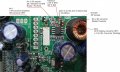
Shorted diodes in the bridge rectifier can also cause the fuse to blow.Check the diodes .If they are shorted,replace and try.
In one SMPS power supply I replaced the capacitor but still the fuse blew.When I checked the diodes in the bridge circuit, I found two of them shorted and they are directly across the supply and causing the fuse to blow off. When I repaced the two diodes it started working fine.
In one SMPS power supply I replaced the capacitor but still the fuse blew.When I checked the diodes in the bridge circuit, I found two of them shorted and they are directly across the supply and causing the fuse to blow off. When I repaced the two diodes it started working fine.
")


