troubleshooting a tv power supply

R!f@@

Joined Apr 2, 2009
10,004
Now comes a bit hard part.
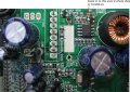
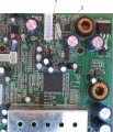
First look at the pic and familiarize the two points I have shown.
1 is the power on off.
2 is the base of the 5V shutdown transistor.

What I want you to do is to measure the voltage at standby and after switching on the TV.
First secure the black probe to a solid ground, cause you will need one hand to switch on the TV from standby.
Remember switching on does not mean turning on the mains power.
Mains should be always on in order to put the TV in standby

So you should post total of 4 different voltages.
at point 1, in standby and switched ON
at point 2, in standby and switched ON
Post the results.

I am trying to avoid removing a SMD component.
 

Attachments

Thread Starter

johndoe45

Joined Jan 30, 2010
364
stand by. what do you mean? i can't connect the tv to the monitor to know if its in standby if thats what you mean. cause the monitor cables are short and case has to be almost closed with all cables connected.

hot gun. no. is that special gun to take out SMD components
 

kingdano

Joined Apr 14, 2010
377
i just want to say that this is an epic thread of debug and analytical skills - especially since it is being done strictly via pictures...impressive stuff.


back at it now fellas.


*applause*
 

Thread Starter

johndoe45

Joined Jan 30, 2010
364
exchanged multimeter for me.

let me see if i understand now.

you want me to push power button on tv with or without monitor on??? cause like i said if need monitor on. i can't probe anything cause the cables from monitor to main board are short (meaning case nearly closed with all cables plugged in).

after i push power button on remote. want me to read voltages with DMM at 1 and 2. but how would i know the tv is on???

then want me to push power button again (meaning its now in standby mode???) and read voltages at 1 and 2.
 
Last edited:

R!f@@

Joined Apr 2, 2009
10,004
The TV should be completely assembled to do this test
Yes. You have to get some one to use the remote to switch on from standby.
u need to keep an eye on the meter when the tv turns on, there should be a change in the reading in atleast one of the point.

When you give power to the TV there should be a red led lit and the TV will be off, the RED led indicated standby. When the remote power button is pressed the RED led will go off and the screen will lit. this will be the ON mode.
Measure one point at a time.
Get my point.
 

R!f@@

Joined Apr 2, 2009
10,004
If you can do the above then do it, if not assemble the TV. Put every thing back as it was.
Keep the back cover open.
Give power and test the screen.
Tell me whether the set responds to the remote.
and also to the buttons.
I am trying to figure out the another way to go about doing this since you don't have a buddy to help
do this and post back
Keep the TV assembled but without the back cover.
 

Thread Starter

johndoe45

Joined Jan 30, 2010
364
alright. didn't think about that. going to have to unmount the power supply. will do this when i get home from school around 5 20 pm gmt-6

i remember one time a long time ago. i took out motherboard while still connected to ps2 so i could lense on dvd drive. accidently left power on ps2. and burnt the carpet. :D

so i was wondering if the bottom side (part without components) can lay on the inside of the case????
like won't damage any components

do i have to plug in dvd drive??? cause that going to be a pain to get off back cover and put it back on.
 

Thread Starter

johndoe45

Joined Jan 30, 2010
364
alright.

at 1
standby=.124
power on=5

at 2
standby=.67
power on=.027

if doesn't make sense. i can double check
 
Last edited:

loosewire

Joined Apr 25, 2008
1,686
riaff,said you have no buddy,I ask again
how far you must be from Texas Expert.
Maybe Texas expert will come forward
and check distance,this is a special post.
Needs special attention,just trying to make
reasonable request,for 4 thousand viewers
of thread.
 

R!f@@

Joined Apr 2, 2009
10,004
alright.

at 1
standby=.124
power on=5

at 2
standby=.67
power on=.027

if doesn't make sense. i can double check
Make perfect sense. The μC is working perfectly. I am not at home, have to check the pics to be sure but the difference in voltage is what I wanted to see. Just checking for updates. This is a good thing,we are close to a fix.

I'll post back with another method to get that DC to DC converter running.
 

R!f@@

Joined Apr 2, 2009
10,004
Take a look at the PIC, a real close up.
For this job u will need a surgical knife, a small sharp pointy knife.

Power off the TV, you might not need to take the board out, cause we will need to power up the TV to check the result
Lightly scrape of the green layer and expose the copper of that orange area I have marked, after this you can see the track that is connected to that transistor.


Now carefully cut the track at the blue line, once or twice slicing will cut the track, don't worry you have nothing underneath that you can cut with that knife.

Thirdly take the digital meter put it in DC resistance mode and connect one probe to that transistor collector pin ( which is the pin you just isolated ), and the second probe to pin 7 of that IC which we tested before ( DC to DC converter). There should not be a low resistance reading, a high resistance in the range of KΩ is fine, if you get 0Ω, then the track is still connected and you need to do some more slicing to isolate the transistor collector.

Next put the black probe on ground and the red one on pin 3 of that IC and measure the resistance.
If you get any resistance close to 0, stop and post back.

If not give power and switch on, if that IC is working then you should see a good picture.
Post back after this
 

Attachments

Top