soldered in the one cap.
ok. ic has 12 DCV at pin 2.
pin1=0
pin3=0
pin4=0
other side starting from bottom
pin5=0
pin6=0
pin7=0
pin8=0
probably not good right?
with continuity test of analog meter. cap beeps both ways. i'll take my meter into sears around 3 o clock. don't think they are going to replace a $200 Fluke DMM without a reciept. Mom lost it. Was birthday gift. Not even 3 months old.
DSP? you used that before. what is that? digital signal processing?
Bad thing is that it's a SMD we are dealing with. ( not to me but to you, the more fault I see the happier I get, so it's always a good thing to me)
Good thing is we have found a fault.
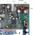
Now the problem is to measure the resistance from the pin 3 of that IC to ground.
Give me the exact DC resistance you get, power should be off, caps discharged, Keep the meter connected for a while to see if it changes, I need you to have the probes touching the IC lead for atleast more than 5 sec.
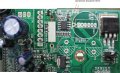
OK time to solder the inductor and cap.
see the PIC.
I inductor track seems damaged, so you need to make sure the IC pin3 has a connection to the inductor..
Remember what you did with the fuse. Just like that.
After soldering use the meter and check pin 3 and inductor has 0Ω.
Time for voltage measurement. I am editing another pic for that.
 Facebook
 Google
 GitHub
 Linkedin