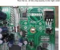
Excellent photo,good lines to show good test points,this project is
getting better.Go Guys--Riaffy you doing the art work,very good
we can expect great things to come in the future.
Does not make sense to me.
Check to see if the chip capacitor has a short across it.
Next check if there is connection from the regulator to the Big capacitor. ( photo shows a connection )
You really have to say clearly what you are trying to say
Excellent photo,good lines to show good test points,this project is
getting better.Go Guys--Riaffy you doing the art work,very good
we can expect great things to come in the future.
If you see a short across the your right most pin of the regulator to it's center pin, then the chip capacitor has a solder bridge.
Renew the solder across it's pins (chip capacitor) to clear the bridge.
Be careful not to apply too much heat as the cap will stick onto the iron tip if you are not fast enough.
A short would say zero resistance and infinite is open or no resistance.
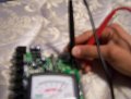
Can you show me a photo of the meter reading while the probe is connected across the chip capacitor.
I think the definition you are giving is misunderstood.
We have to clear how your meter reading is taken
Which means there won't be voltage available at the input of the regulator.
The chip is producing a path to ground.
There are possible 3 reasons for this.
1. The chip is shorted.
2. The regulator input is shorted.
3. The chip capacitor could have solder bridges from the looks of it.
Look at the picture and follow the below procedures
1. Solder E3 ( electrolytic capacitor 3 ) only and leave the other cap and inductor out for now.
2. Assemble the TV and plug in all the necessary cables ( we are going to power up the TV ). Remember only two components should be left out.
3. Power up the TV.
4. Put the meter in DC 20V range, Connect the black probe to the ground or on the metal plate of the main board. This is a solid ground or the negative pin of E9 will also do fine.
5. Measure the voltage at pin 2 of U4 ( pin 1 is near the label U4) IC , see the picture. You should have 12V, as this is connected to the fuse. If 12V is not there, check the fuse. You should have 12V as before. Remember the previous posts.
Follow the procedure below if no. 5 above passes.
6. Measure and post all the voltages at the pins of IC U4
not anymore. have to take it back to sears. don't have reciept though. must have gotten miscalibrated or something.
so telling me a cap having a small ohms reading both ways is shorted. and a good cap has one low ohms and one high ohms reading?
is there a good DMM that will test almost everything like caps (not just capacitance but to see if its good like ESR meter), transistors, diodes, resistors, etc?
You need to tell what part you are going to test, so you can be sure
someone tells you the right Instrument. Some will agree that a
analog meter will show you more on a test. The better the meter,
the better the Information you can get. Like a filter cap If good
the will swing over and come back,you can't see that on ditital.
A matter of chioce,the more you can see ,the more you under stand.
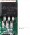
Sorry to jump in on the conversation here, but I had noticed something on the pics of the board that I don't think anyone has seen, it seems as if the op has a blown transistor on the board next to the fuse...... there is a good chunk of the transistor gone on one side....
Thanks BMorse. I did missed that, but I don't think that is the main problem here,
The transistor still might work.
Joseph, take a look at the picture I have combined and edited 3 pictures.
The chipped part could not be the cause, for that pin uses 12V too. For now we will leave it as it is. As u can see the 12V rail goes from the fuse and to the IC. Now I think it is a DC to DC converter.
It takes in 12V and gives a 5V. The out put diode is on the back side and the inductor is on the top.. This 5V is given to that 3.3V regulator.
Without the 5V the mainboard has no supply to it's DSP.
Now from ur measurements the chip cap shows a short, which will shut down the 5V converter.
What I am wondering is why there is a solder bridge, if there is, in the first place.
After seeing the converter voltages I can decide what to do next.
But I think you should get a digital Multimeter. It will make things easier for u and me.
The trouble we are having is the way we communicate. I am having a hard time understanding your measurements and readings. Sometimes a 1 is a short and sometimes it's open. Specially the resistance readings.
You need to be confident in your ability to measure the resistance using an analog meter. Which I think is the hardest part for any one.
That's why DMM diode check and continuity modes comes in handy.
Any ways, we are making progress.
I just hope that main board does not have a SMD device fault.
Cause if it did, then I wonder how you are going to remove it.
Remember tester.
 Facebook
 Google
 GitHub
 Linkedin
 322 KB Views: 32
")