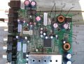
it turns on. no sound. maroon color picture. dvd player not working. dvd player might be cause i hooked it up wrong but everything else is hooked up right
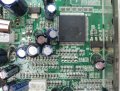
Marking indicates a 3.3V regulator. And power is not coming to it.
Bad news.
Now, don't go and take out the components like tester2 did.
Wait till I say so.
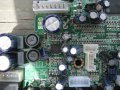
So, we need to find why this regulator have no input.
Do you think you can trace it?
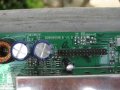
Yea. U need to find the input pin connection and where it leads.
This way you can figure out where the connection is broken or from where the regulator get it's input Vcc.
We need a positive voltage for this regulator. It should be coming from somewhere.
Where is what we need to know. Since you have the board you can take closer look and trace the tracks
This I will leave it to you, let's see what you are made of.
I am off to bed, it's been 36 Hrs without sleep.
See u tomorrow.
G night
ok. i will try either later on today or tomorrow. so by tracing. you mean go through the traces and find where the voltage stops?
meaning the defective component will have a voltage on one side but not the other.
i don't know anything about circuits besides all the googling. researching. physics II class and Lab I took which had a little bit of capacitance, resistance, current, and voltage calculation of series and parallel circuits. been about a year and half since i took that class so don't remember too much.
the problem i have is looking at a PCB and imagining a schematic of it. Like how to tell what is parallel and in series on a real board. Not just some drawing.
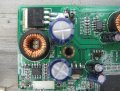
The Input should connect to the 12V through a component, there may be a MOSFFET switch in between.
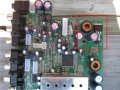
I have to take closer look at that area. The picture you gave, some components are blocking the view, I need a direct view from the top. so the caps and inductors aren't blocking the PCB
i am more confident in my soldering ability now. i don't put pressure on the pad and did fine on taking off the plastic part earlier.
those are the capacitors i was talking about. was doing in circuit tests with the resistance and capacitance which doesn't tell you anything cause they are in circuit. but usually the capacitance is correct when i probe them in circuit. but these didn't add up. i don't know. ignore this cause will probably just throw you off and might not be problem.
 Facebook
 Google
 GitHub
 Linkedin