ok. just desoldered fuse and tested from the + terminal of the connector and was 114 VAC and at first fuse pin with fuse out was 114VAC.
continuity test on the + and - power input fails
and bridge. you mean want me to unbridge these even though they were like that already????
its actually 57 VAC at 2 bridge pins and input output voltage connecters. like half of what i'm supposed to get. is it cause the FET and bridge is out. when i measure at the FET pins of the one that is out i get .0485 VAC. why am i picking up voltages past the bridge?
I'm making a schematic for it. will take a little time,
I'll mark the schematic so that you can follow very easily.
The problem you are having does not make sense.
I have some jobs to attend to. keep checking this thread daily
the fuse passed the continuity test. its just when i isolate the circuit by taking the fuse out. i get the 114 VAC at the + terminal and when i solder the fuse back in i get 57 VAC.
114VAC is correct because most power supplies start at 115 VAC. am i correct?
so something in this section is bringing the voltage down.
taking all three blue caps out tomorrow when get desolder pump and maybe new iron. but i read when at the full voltage is when you can tell if the capacitor fails.
i will check this thread daily. thanks for your help.
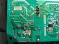
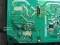
okay the two blue capacitors that are near each other read 1nF which is the rating. but my DMM's lowest reading is 1nF so hard to tell if it is correct. on the other blue capacitor (off picture near input) is 470 pF which is lower than my DMM's lowest reading. but DMM still reads 1nF. the FET tested fine and desoldering all diodes in this section now.
Do i need to take out the resistors???? or can i check them from topside since can probe them from both sides.
ok there is a black cover over resistor (next to filter cap) so i don't know what the value is. but it is only like 0.4 ohms on my DMM. this is without soldering it out. will do that tomorrow. so could resistor be causing the low voltage since V=IR.
the bridge shorted. y didn't you tell me i was doing test wrong
post #20
real way to test a bridge is connect + and ac and switch probes. only one reading should show
connect - with other ac and only one reading should show.
connect both ac and switch polarity, should be no reading.
Do not put the bridge or FET, leave them out.
Plug in the cable and measure the AC voltage at the connector of the supply. by connector I mean the jack which power comes in to the PCB.
cause i can't get to the jack topside cause its covered with white stuff
if so then it is still the 57 VAC with fuse in, bridge and FET out. Like i said though. when i take out the fuse and leave bridge and FET out. the voltage at the pin in picture returns to 114 VAC. weird
this is picture from previous post. Bridge and FET are still out
This is going to be a bit difficult, I want you to take two piece of wire and solder it to the PCB jack pins.
Next apply power through these wires.
Mind you, to get proper insulated wires and connect a plug or atleast have secure connection when you are doing this.
Since you have taken the liberty to tackle the SMPS, I am assuming that you know the proper handling technics and the dangers involved around mains voltage.
Take every precautions, if in doubt, stop and post back
 Facebook
 Google
 GitHub
 Linkedin
")