troubleshooting a tv power supply

R!f@@

Joined Apr 2, 2009
9,918
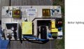
Don't worry about the black and white stuff, they are glue.
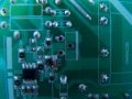
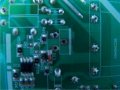
A poor soldering might not damage the components as it might not heat up to that temp. but will make desoldering a pain in the butt.
You should get a better Iron to speed things up. mean while get a another pic from the solder side, a real close up of the supply , same position as in the first pick of post 20, but the other side
 

R!f@@

Joined Apr 2, 2009
9,918
Seems to me the bridge is fine.
So solder it back and put a new fuse but leave the FET out.
Power it up to see if the fuse blows, if not I need you to check the drain voltage.
Measure between the smoothing cap negative and drain of the FET, it should be close to 300VDC if your main supply is 220VAC.
If 120VAC then it should be close to 150vDC.

Be careful, as you a playing with lethal voltage, take every precaution.
Since you have taken the board and tried to fix it your self in the first place I am assuming you know how to get around high voltage and main supply too.

I am attaching the PDF of the FET for ur reference
 

Attachments

Thread Starter

johndoe45

Joined Jan 30, 2010
364
ok. i will do that as soon as possible. and the FET. how do i check the voltage?

how to get around high voltage? you mean just don't touch anything with my fingers? and don't do a resistance test with the supply on and make sure meter is grounded? i have antistatic wristband too.
 

R!f@@

Joined Apr 2, 2009
9,918
Refer to the pictures attached.
From the top side, get a clear pic so that I can see the components from the top side.
De solder the FET and leave it for now
when you zoom in to the solder side of the picture you can see the markings.
Raw DC will be at the capacitor positive and negative. If you afraid to probe them live, then solder a wire to the negative side of the cap and clip it to the meter negative . get a long wire for safety.
put the meter in 500VDC range (approx).
Replace the blown fuse with a new one, remember to use slow blow type, or else the fuse will keep blowing for no reason. check it for proper current rating.
With the negative side of the meter connected, use one hand to hold the positive probe. Keep the other hand at the power switch. ready to switch off the power to the board if any thing should go wrong.
Now give power and measure the voltage at
1. capacitor positive
2. Drain voltage
3. Source voltage
4. Gate voltage.

When measuring gate voltage you have to decrease the DMM range.
Gate voltage will be at around 0.5 V to 1.5 V DC or so, and it should be pulsing.
Pulsing will cause the DMM reading to fluctuate, an analogue meter will give a better view of th AC gate voltage.

Remember these things are taken if the fuse does not blow and also that you get a Raw DC voltage at the cap. Otherwise there will be nothing.

PS. Wrist band won't do you any good here unless you are at high static area.
Do not touch with your figure on the primary side, Lethal voltage will be present.
Always use one hand when probing primary side of any SMPS.
Keep the board stable and you should also be stable, any mishap here might cause injury or further damage to the board.
And if you touch the filter cap terminal with ur finger, it will burn in like a hot needle :eek:

And be sure that the DMM is in DC Voltage Range.....if in resistance range then you can bid farewell to ur meter :D
 

Attachments

Last edited:

Thread Starter

johndoe45

Joined Jan 30, 2010
364
i gave you a brighter picture in post 20. i ran out of fuses so will go get one in an hour. only have fast acting. if current rating is 3.15A can I get a 3A???
 

Thread Starter

johndoe45

Joined Jan 30, 2010
364
a 4A slow acting right?

i am a beginner. does my soldering job look crappy? look at the rectifier. be honest. and how could i make it cleaner or better.
 

Attachments

Last edited:

R!f@@

Joined Apr 2, 2009
9,918
Soldering is kinda ok.. but too many solder.
Show me your iron. I think not enough heat.
What type of solder do you have?

Fuse slow ...fast does not matter......just for the test
 

R!f@@

Joined Apr 2, 2009
9,918
one more thing.
The filter cap will hold charge for a few hrs.
So be careful when handling the board.
Get a resistor around 470 ohms to discharge the cap after power down
 

Thread Starter

johndoe45

Joined Jan 30, 2010
364
i'm a little lost. told me to desolder the FET, so did you mean to resolder the FET in with the fuse and then test the gate drain and source? and where would i clip the ground just to make sure i'm not doing this wrong. and i check the capacitor with the fuse and FET?
 

R!f@@

Joined Apr 2, 2009
9,918
Leave the FET out .
Just solder the bridge and fuse.
Keep the FET area clean from solder and solder bits. What you have is a surface mount board so after desoldering you should always clean the board using a brush dipped in thinner or alcohol. This will prevent accidental shorts.
The ground is the reference point for the voltage measurements and it is the filter caps negative. Period.

Your iron is too small for that kind of job, If you are going to do this regularly then get a temperature controlled one.
Solder is fine....60/40 0.8mm will be suitable for most of the regular jobs.
 
Last edited:

Thread Starter

johndoe45

Joined Jan 30, 2010
364
so how do i check the drain gate source when the FET is out. that means all i will be able to check out of what you told me is the capacitor positive?
 

R!f@@

Joined Apr 2, 2009
9,918
No.. Please read my post carefully and you will understand. I need the measurements to figure out why the fuse is blowing
Even though the FET is out the PWM will produce the start pulses and u will get voltages
 

Thread Starter

johndoe45

Joined Jan 30, 2010
364
alright one more question. sorry. so i plug it in like i normally would and then just take the voltages. i lost part of the metal plate from desoldering. like that metal ring that you heat up to apply the solder. so would it still pick up the voltages. taking a picture now.

this is best lighting i could get. its dark outside.
 

Attachments

Last edited:

Thread Starter

johndoe45

Joined Jan 30, 2010
364
reread last post edited it and sent picture. look at the FET. isn't there supposed to be a metal ring. or how would i test those areas when there is no part there?
 

Attachments

R!f@@

Joined Apr 2, 2009
9,918
The metal ring :D.
Those were the copper tracks, it will come of due to improper desoldering techniques. Since you are a noob, that is bound to happen :rolleyes:.. no worries.
You will get the hang of it.
Desoldering and soldering is like an Art. you have to master it through practice. It depends on the pressure that you apply, the type of solder that you use, the type of pump and how you handle the pump together with the iron, plus the soldering gun that you use.
All these things make you a good tech. keep that in mind :cool:

The rings came off becuase your gun's heat is not regulated and also you might be applying too much pressure on the pad.
Zoom in the picture, I have circled the 3 pins, just take a surgical knife and slightly scrape of the green solder mask from the area that I have circled until you can see clean copper. Too much pressure and you will damage the board, so be patient and do it slowly. Ones when can see the bare copper pads, there you can solder the FET pins, and it will be OK.

The FET voltage measurement have to be taken without the FET. Just ground the negative and touch the positive probe in those areas that I have circled. one by one and measure, there is nothing to it. forget about the FET for now OK. Just be careful not to slip the probe since drain will be at a high voltage and if you accidentally touched the gate with the drain, then ur PWM will hit the bucket :D for good. And you will be in a bigger hole than before.
 

Attachments

Thread Starter

johndoe45

Joined Jan 30, 2010
364
ok. i tried to measure it but cap voltage kept dropping so skipped to the drain and kept dropping. think fuse blew. it is disconnected can i do a resistance check on the fuse to see if its good? or is it dangerous still?

cap was at like 90 something. maybe higher. was using the fluke digital and was just not accurate. by the time i switched to the analog. i think fuse died.
 
Top