Troubleshooting a circuit to drive an old railway clock

sghioto

Joined Dec 31, 2017
8,729
Curious, though - why not leave the 4K7 resistors as-is and increase the input resistor from 120R to something like 390?
There's actually no need for the 120R resistor.
It's simply in series and doesn't add any significant value to the total resistance off the 120 volt line.
 

AnalogKid

Joined Aug 1, 2013
12,224
Schematic #51 - Why not delete the 555 (!!!) and connect IC2 pin 6 directly to the R2/C2 node. It easily can drive the 100 K resistor, but LED resistor R2 would have to increase. Still, one less 555 in the world.

ak
 

sghioto

Joined Dec 31, 2017
8,729
Schematic #51 - Why not delete the 555 (!!!) and connect IC2 pin 6 directly to the R2/C2 node. It easily can drive the 100 K resistor, but LED resistor R2 would have to increase. Still, one less 555 in the world.
ak
Because pin6 of IC2 when High resets IC1. The pulse is too quick to activate FET2.
Besides you know how much I like the 555s.
:D
 

Tonyr1084

Joined Sep 24, 2015
9,744
Because pin6 of IC2 when High resets IC1. The pulse is too quick to activate FET2.
That has been a constant concern for me as well. Resetting too quickly and watching the pulse go away before the escarpment could activate the clock.

I had thought about using a binary counter too. That and some AND gates. You used a Dual 4-input NAND gate and a second gate as a buffer. The line of thought I had was to use a Quad 2-input chip. Two of the AND's could be used as a single 4-input by configuring two and two into a third "2-in making a single 4-input AND gate. The fourth AND could be used as a buffer if necessary. But the third stage AND would have been sufficient to drive the FET. Let me draw a picture for anyone who doesn't follow what I'm saying:
View attachment 360683
Not that this is any better; It's just what I have more than half a dozen. The inputs to U1-D are grounded.
 

sghioto

Joined Dec 31, 2017
8,729
Sure, that would work as well.
But still need to reset the timer.
I copied that circuit from the data sheet for the MC14040.
The second half of the 4 input nand gate is used as an inverter to provide a High output for the reset.
What I liked about the MC14012 is it provided a Low output on pin8 to trigger the 555 pulse stretcher.
 

Thread Starter

Doctor_Ed

Joined Feb 10, 2022
72
I used the schematic in post 28 but modified with the detail in post 57.
OK, I have to report that the device is not keeping time. It is running very fast, by about 25-30%. The speed is different with and without load - much faster with load. There seems to be some signal feedback happening. When FET2 and FET3 are energized (on for 10 sec), LED1 speeds up for those 10 sec.

The breadboarded version ran accurately, but not the PCB version. I can't see any difference in the connections.
 

sghioto

Joined Dec 31, 2017
8,729
That's strange.
Is the 5 volt regulator stable?
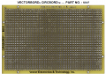
Can you post a photo or image of an unpopulated circuit board to verify it's accurate?
 

Thread Starter

Doctor_Ed

Joined Feb 10, 2022
72
That's strange.
Is the 5 volt regulator stable?
Can you post a photo or image of an unpopulated circuit board to verify it's accurate?
Actually, there was one difference in the circuits - in the breadboard version, I used a 0.1 μF cap between pins 5 and 8 of the optocoupler, but skipped it in the final as it seemed redundant.

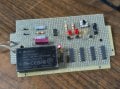
The voltage is steady at 5.04V. The circuit board is as follows.

1767664861742.png
 

Thread Starter

Doctor_Ed

Joined Feb 10, 2022
72
I thought you had a custom pcb fabricated.
From the data sheet:
View attachment 361679
Reinstall the cap.
No custom PCB. I put in a 0.2 μF (couldn't find the 0.1). Note it is in parallel with the existing 1 μF and 47 μF caps. Made no difference. The first LED is still blinking at about 43/min instead of the required 36, and still speeding up when the last counter is triggered.

I will just have to go through every connection meticulously step by step to discover what might be wrong.
 

sghioto

Joined Dec 31, 2017
8,729
Try removing the 1 and 47uf caps and use the 0.2uf cap only.
Something must not connected correctly if the count is incorrect.
Double check all connections on that vector board specifically looking for cold solder joints and shorts.
 

Thread Starter

Doctor_Ed

Joined Feb 10, 2022
72
Try removing the 1 and 47uf caps and use the 0.2uf cap only.
Something must not connected correctly if the count is incorrect.
Double check all connections on that vector board specifically looking for cold solder joints and shorts.
Right. I appreciate your suggestions. I have to retire now, back at it soon.
 
Top