Troubleshooting a circuit to drive an old railway clock

Tonyr1084

Joined Sep 24, 2015
9,744
Ignoring FET2 and the LED, even with the current information, I think you'd want a 2 input AND gate (or transistor equivalent) to do a complete reset of CD3 & 4. Only when a certain set of circumstances will reset the two counters.
View attachment 360500
And I'm still having trouble envisioning how this would work.

WAIT! CD3, pin 1 to pin 15 resets after six counts. OK, yes, that's correct. Ignore my jumper from CD4 pin 5 to CD3 pin 15. The above should reset after one second. Assuming the RC circuitry is correct.

Awe heck! I'm going to go see if there's a good football game on TV.
 

Thread Starter

Doctor_Ed

Joined Feb 10, 2022
72
Thanks for all the suggestions. The rig is working but the timing is bad.

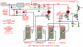
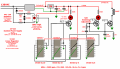
Note the current schematic.

Clock Driver 60hz Corrected2.png

The load should be energized once per 60 seconds, but instead initially it is about 55 seconds, and then gradually shortens over the next few minutes to around 40 sec between events.

I'm noticing that the LED at FET1 is flashing irregularly and much faster than it should. So the problem is there or earlier.

When I connect a 0.068 µF cap to the signal at CD1 pin 14, the signal unexpectedly speeds up by about a factor of 4. It is hard to tell at about 2 or 3 flashes a second, but I think it is still irregular. However, it no longer speeds up with time.

All very bizarre.

Pin 12 (carry-out) is not connected on any of the counters.

The ratio of pulses from CD2 output to the load is 36 as far as I can tell, so the last two counters seem to be working properly.
 

bertus

Joined Apr 5, 2008
22,985
Hello,

Is the input clock stable?
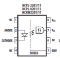
The datasheet shows an input forward voltage of 1.5 to 1.7 volts at 5 mA.
You have two diodes that limit the voltage to 1.4 volts.
Add an extra diode to limit the voltage to 2.1 volts.
Also add an reverse diode accross the three other diodes.

Bertus
 

sghioto

Joined Dec 31, 2017
8,737
Another potential error.
When first powered ON pin3 on all 4017 chips is normally high, this will immediately send a pulse to CD2 and CD3 advancing the count prematurely.
That's assuming all 4017 chips start at zero when first powered which isn't always the case.
 

Thread Starter

Doctor_Ed

Joined Feb 10, 2022
72
Hello,

Is the input clock stable?
The datasheet shows an input forward voltage of 1.5 to 1.7 volts at 5 mA.
You have two diodes that limit the voltage to 1.4 volts.
Add an extra diode to limit the voltage to 2.1 volts.
Also add an reverse diode accross the three other diodes.

Bertus
The opto-logic and its connections might be the problem. I am measuring 1.9 volts at terminals 2 and 3, but with + on 3 which is supposed to be the cathode. Without my probe that voltage is probably well over 2v. If I reverse my connections to pins 2 and 3 of the opto, nothing works.

1765747591352.png
 

MisterBill2

Joined Jan 23, 2018
27,976
I suggest going back and reading te WHOLE DATA SHEET and understanding the output capabilities of the CDE4017 powered by FIVE VOLTS. The counts outputs can source maybe ONE MILLIAMP. THAT is for good quality devices, not copies or clones. So feeding RC circuits with high impedance outputs may not may not work as you wish.
 

Thread Starter

Doctor_Ed

Joined Feb 10, 2022
72
On a whim, I reversed the 120 VAC input leads, and now it runs better. I'm getting an actuation every 56 seconds now instead of 40 or 50. I guess I have a noisy AC line.

It's still not right, though, so I have to figure out how to calm the AC.

This result also indicates that the first two counters really are dividing by 10 and not 9.
 

MisterBill2

Joined Jan 23, 2018
27,976
Why struggle with stacking decade counters when the same one per minute can be provided by a single decoded binary counter?? Two IC devices for the whole thing. An MC14040B 12 bit binary counter and an MC14082, a dual 4 input AND gate. Much simpler and not nearly so challenging as a four stage divide by 3600 (6x10 x6x10) . And even though it is a ripple counter, the 18 millisecond clock pulse interval will allow adequate ripple time. An added benefit is that the. same chain can provide the signal to switch OFF that 24 volt pulse, So why struggle.?? the pulse can set the output voltage control FF and rest the counter and then a slightly later count pulse can reset the FF. NO ADDED COMPONENTS!!
 

Thread Starter

Doctor_Ed

Joined Feb 10, 2022
72
Why struggle with stacking decade counters when the same one per minute can be provided by a single decoded binary counter?? Two IC devices for the whole thing. An MC14040B 12 bit binary counter and an MC14082, a dual 4 input AND gate. Much simpler and not nearly so challenging as a four stage divide by 3600 (6x10 x6x10) . And even though it is a ripple counter, the 18 millisecond clock pulse interval will allow adequate ripple time. An added benefit is that the. same chain can provide the signal to switch OFF that 24 volt pulse, So why struggle.?? the pulse can set the output voltage control FF and rest the counter and then a slightly later count pulse can reset the FF. NO ADDED COMPONENTS!!
I appreciate what you are saying, but I don't have the skills to design a circuit like that.

I figure I'm 90% of the way to a rig that works now, so not too motivated to start over.

We should have talked before!!
 

eetech00

Joined Jun 8, 2013
4,723
On a whim, I reversed the 120 VAC input leads, and now it runs better. I'm getting an actuation every 56 seconds now instead of 40 or 50. I guess I have a noisy AC line.

It's still not right, though, so I have to figure out how to calm the AC.

This result also indicates that the first two counters really are dividing by 10 and not 9.
Like I stated in my previous post. The 1N4004 diodes should be connected anti-parallel to the Opto LED. Otherwise, the diodes just short circuits the AC line current away from the opto LED. I don't think the two parallel diodes are even needed. But be careful around AC line voltage.
 
Last edited:

Thread Starter

Doctor_Ed

Joined Feb 10, 2022
72
Like I stated in my previous post. The 1N4004 diodes should be connected anti-parallel to the Opto LED. Otherwise, the diodes just short circuits the AC line current away from the opto LED. I don't think the two parallel diodes are even needed. But be careful around AC line voltage.
Sorry, I didn't know what "anti-polarity" meant, and I'm a bit fuzzy on "anti-parallel". So I would just reverse one of them? Or reverse both? The easiest would be to remove them. I guess that would put around half of 1.5v (RMS) on the opto.
 

MisterBill2

Joined Jan 23, 2018
27,976
Incoming power filters are common and there are quite a few of them appearing in past threads on this site. I am sure there is a way to search for them, somebody else who knows how should be able to help you use it.
 

Thread Starter

Doctor_Ed

Joined Feb 10, 2022
72
OK, I removed the diodes in parallel to the opto-logic. It runs very well now, with close to 60 sec between cycles. But oddly enough it isn't exactly 60 sec but 59.77 sec. The device gains about 14 sec per hour. That's about 6 min per day. Could that reflect variance in the AC frequency? Doubt it, but I will check it again later.
 
Top