Troubleshooting a circuit to drive an old railway clock

Thread Starter

Doctor_Ed

Joined Feb 10, 2022
72
Incoming power filters are common and there are quite a few of them appearing in past threads on this site. I am sure there is a way to search for them, somebody else who knows how should be able to help you use it.
Thanks! There is info for them online. I might try something like a 10 or 20 µF cap across the 120 VAC terminals and see if it helps.
 

Tonyr1084

Joined Sep 24, 2015
9,744
I have two clocks that both gain time over not so long periods. MOST of my clocks seem to run fairly accurate but of the two, and I don't know how they're clocked, seem to gain a minute and a half every month.

I seem to remember, and this may be inaccurate, one clock that had a tap from the AC line - if for nothing else - to provide a 60Hz signal. I don't have the equipment to get an accurate measurement of my AC frequency but I'd be willing to bet it's more on the 60+ Hz side; whatever that may be.
 

MisterBill2

Joined Jan 23, 2018
27,977
That count is close to it missing one mains cycle per minute. (about 18 milliseconds per cycle. So instead of 3600 cycles count you are getting 3599 cycles count. That implies triggering one count too early. or resetting the first stage to a count of one instead of a count of zero.
 

Futurist

Joined Apr 8, 2025
925
@Doctor_Ed

Surely there are simpler solutions. What drove the clock originally? how about a picture of this clock, any labels, dates etc, just how old is the clock? where did you get it?

Really some background and historical data would be appreciated, perhaps its Swiss? I read about that design, these clocks ran a second or so fast and the second hand would freeze at 12 "waiting" for the next pulse, all Swiss rail station clocks were synchronized from a central source it seems.

I'd consider using a crystal controlled oscillator for this or even a little 1 RPM AC gear motor as the timing source, perhaps driving a micro switch (giving it an electromechanical character).
 
Last edited:

Futurist

Joined Apr 8, 2025
925
Look:

1765810293556.png

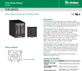
You can set the on/off interval and it repeats so long as power is applied, it drives an internal 10A relay - this is basically your problem solved.

You'd set these "off" switches to: 32, 16, 8 and 2 and 1 = 59 seconds off exactly and set the "on" switches to simply 1.

If you need the on pulse to be short, say 0.1 second, then just get the other range, that can let you set a 59.9 off time and a 0.1 on time.

That gives you a 1 (or 0.1) second on pulse followed by 59 (or 59.9) seconds off, repeating.

Littelfuse® SSAC® TDR4A12 Recycling Time Delay Relay
 
Last edited:

Thread Starter

Doctor_Ed

Joined Feb 10, 2022
72
@Futurist - never knew about this. Buying off the shelf is almost always better than making your own. Seems like overkill, but as you say, problem solved.

There are many ways to do this. I had a synchronous motor device for a time, but the contacts wore out. Went to a reed contact and that fixed it, for a while, but then it too became unreliable. Then I figured, solid state is the answer. It's all simple until you build it.

My device is still running fast, consistently by about 0.35% (=5 min/day).

I will check out the relay. Thanks.
 

Futurist

Joined Apr 8, 2025
925
@Futurist - never knew about this. Buying off the shelf is almost always better than making your own. Seems like overkill, but as you say, problem solved.

There are many ways to do this. I had a synchronous motor device for a time, but the contacts wore out. Went to a reed contact and that fixed it, for a while, but then it too became unreliable. Then I figured, solid state is the answer. It's all simple until you build it.

My device is still running fast, consistently by about 0.35% (=5 min/day).

I will check out the relay. Thanks.
Yes, but I understand the attraction of building something myself but I often have to temper that urge, I try to reserve that for truly unusual scenarios.

The device seems priced around 150 bucks, bit pricey but problem solved, period.
 

sghioto

Joined Dec 31, 2017
8,737
Buying off the shelf is almost always better than making your own. Seems like overkill, but as you say, problem solved.
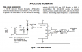
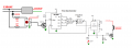
Probably too late but for prosperity.
Have to give credit for this design to MisterBill2 if still interested in building your own.
5 volt regulator not shown for simplicity.
Circuit derived and modified from the MC14040B data sheet.
IC3 extends the output pulse from the timer to appx 1.1 seconds to illuminate LED1 and drive clock mechanism.
1765828733837.png
1765937861167.png
 
Last edited:

Thread Starter

Doctor_Ed

Joined Feb 10, 2022
72
Probably too late but for prosperity.
Have to give credit for this design to MisterBill2 if still interested in building your own.
5 volt regulator not shown for simplicity.
Circuit derived and modified from the MC14040B data sheet.
IC3 extends the output pulse from the timer to appx 1.1 seconds to illuminate LED1 and drive clock mechanism.
View attachment 360605
View attachment 360606
Thank you for this - interesting. I will check it out.

It's never too late. Reminder that problems aren't solved until they are solved.
 

MisterBill2

Joined Jan 23, 2018
27,977
My results for getting a divide by 3600 involved more bits. So I needed a 7 input and gate.
I used counts of 2048, 1024, 256, 128, 32, 8, and 4. But it was wrong! Doing math too late at night.
Post#51 is correct. Only four bits required.
BUT use a CD4013 FF to set the pulse on and Q6 to reset the FF and switch the pulse off.
No RC time constant on a 555, and no need for an RC pulse stretcher for the MOSFET.
Put both of the 4013 FFs in parallel for more gate drive.
 

sghioto

Joined Dec 31, 2017
8,737
BUT use a CD4013 FF to set the pulse on and Q6 to reset the FF and switch the pulse off.
No RC time constant on a 555, and no need for an RC pulse stretcher for the MOSFET.
Put both of the 4013 FFs in parallel for more gate drive.
I would respectfully disagree with using the CD4013.
The 555 IMHO is just as effective.
 

sghioto

Joined Dec 31, 2017
8,737
Certainly the 555 scheme is as effective but it adds two capacitors and two resistors.
Only 1 cap and 1 resistor used on the 555.
R2 needed for the LED.
C2 may not be needed, was feeding off the original circuits "Soft Start" idea.
The clock mechanism probably requires just a short pulse which can be configured using the 555 circuit thus eliminating C2 and R4.
 

Thread Starter

Doctor_Ed

Joined Feb 10, 2022
72
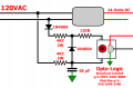
OK folks, I think I have solved the problem. The AC line was noisy, which required some changes to the input to the opto-logic. Removed one of the parallel diodes and flipped the polarity of the remaining one, and added an old fossilized 68 pF ceramic capacitor from the bottom of one of my drawers.
Clock Driver 60hz Corrected5 detail.png
The timing seems solid now. I still need to let it run for a day or two to make sure it is counting 3600 pulses per minute and not 3601 or 3602. But for now it looks good.

Thanks for the discussion and ideas.

As always, the last 10% takes 90% of the effort.
 
Last edited:

MisterBill2

Joined Jan 23, 2018
27,977
GOOD THINKING to consider line noise as the cause. And a good fix as well. Caution: The line noise in the final location may be different, possibly requiring even more measures of locking.
 

Thread Starter

Doctor_Ed

Joined Feb 10, 2022
72
Hello,

I have calculated a peak current of 17 mA in your circuit.
The recomendated input current is 5 mA max.
I would raise the values of the 4k7 to 15k.
See the datasheet for more info.

Bertus
OK, I replaced a 4K7 with a 15K, and doubled the 4K7 resistors for 9K4 on the other side. Time tracking seems good still. I'm also thinking about increasing the value of the capacitor, but 68 works for now. Thanks.

Curious, though - why not leave the 4K7 resistors as-is and increase the input resistor from 120R to something like 390?
 
Last edited:
Top